KRAL OMS Series Operating Instructions Manual
High-viscosity liquids
Hide thumbs
Also See for OMS Series:
- Operating instructions manual (48 pages) ,
- Operating instructions manual (28 pages)

Subscribe to Our Youtube Channel
Related Manuals for KRAL OMS Series


Summary of Contents for KRAL OMS Series
- Page 1 Operating instructions KRAL flowmeters. Series OMS High-viscosity liquids OIO 31en-GB Edition 2024-03 Original instructions www.kral.at...
-
Page 2: Table Of Contents
Table of contents 1 About this document........... 3 9.2.1 Cleaning the pipe system ....... 18 9.2.2 Checking the function........18 General information............ 3 9.2.3 Commissioning the flowmeter ......18 Target groups ............. 3 Decommissioning ............19 Symbols..............3 9.3.1 Switching off the flowmeter ......19 1.3.1 Danger levels .......... -
Page 3: About This Document
1 About this document 1.1 General information 1 About this document 1.1 General information These instructions form part of the product and must be kept for future reference. Furthermore please observe the associated documents. 1.2 Target groups The instructions are intended for the following persons: o Persons who work with the product o Operator-owners who are responsible for the use of the product Persons who work with the product must be qualified. -
Page 4: Danger Signs
1 About this document 1.4 Associated documents 1.3.2 Danger signs Meaning Source and possible consequences of non-observance Electrical voltage Electrical voltage causes serious physical injury or death. Raised load Falling objects can result in serious physical injury or death. Heavy load Heavy loads can result in serious back problems. -
Page 5: Safety
2 Safety 2.1 Proper use 2 Safety 2.1 Proper use o Flowmeter solely for flow measurement of lubricating liquids that are chemically neutral and that do not contain gas or solid components. o Flowmeters require operation with clean liquids. If coarse soiling, solid particles in the liquid or ab- rasive fine particles occur during operation, the flowmeter must be protected additionally by a cor- respondingly dimensioned operating filter in the pipe system. -
Page 6: Identification
3 Identification 3.1 Type code 3 Identification 3.1 Type code 1 Series 2 Size OMS-020.CAEAAA.0029 3 Sensor equipment (pick up) 4 Function of the sensor equipment 5 Bearing material 6 Seal material Fig. 1: Type code 7 Mechanical connection 8 Electrical connection 9 Version index Item Designation Description... -
Page 7: Technical Data
4 Technical data 4.1 Operating limits 4 Technical data 4.1 Operating limits The values specified on the rating plate apply, as well as the values on the calibration certificate if the optional calibration of the flowmeter was ordered. The permissible operating limits of individual values influence each other so that every application is checked individually by the manufacturer when selecting the flowmeter. -
Page 8: Pick Up
4 Technical data 4.4 Pick up 4.4 Pick up For OMS version "standard resolution" with pick up BEG 44, observe the operating instructions for the pick up. Unit OMS-020 (high resolution) Supply voltage U [VDC] 10 – 29 Closed current [mA] <... -
Page 9: Dimensions And Weights
4 Technical data 4.6 Dimensions and weights 4.6 Dimensions and weights 4.6.1 Pipe thread (BSPP thread) Pipe thread Outer diameter Total length Length of the flowmeter without connections Max. screw-in depth Fig. 5: Dimensioned drawing pipe thread (schem- atic diagram) Unit OMS-020 (high resolution) OMS-020 (standard resolution) [inch]... -
Page 10: Function Description
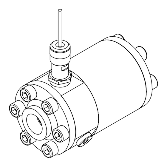
5 Function description 5.1 Structure 5 Function description 5.1 Structure Fig. 6: Flowmeter design (OMS "standard resolution" version) Mechanical connection Small measuring screw Electrical connection Large measuring screw Pick up Pole wheel Measuring housing Intermediate flange O-ring 5.2 Functional principle Flowmeters belong to the group of rotating displacement meters as screw meters. The pumped liquid makes the measuring unit rotate. -
Page 11: Recognition Of Flow Direction
6 Transportation, storage 5.4 Recognition of flow direction 5.4 Recognition of flow direction In the case of systems with pressure pulsation a reversal of the flow direction can occur briefly. o OMS "high resolution” version The flowmeter is equipped with a two-channel pick for flow direction detection. The flow direction can be determined by means of the additional phase-shifted signal and then taken into account for the calculation of the total values. -
Page 12: Installation, Removal
7 Installation, removal 7.1 Dangers during installation 7 Installation, removal 7.1 Dangers during installation The following safety instructions must be observed strictly: o Have all work only carried out by authorized qualified personnel. o Do not take apart the flowmeter. 7.2 Dangers during removal The following safety instructions must be observed strictly: o Have all work only carried out by authorized qualified personnel. -
Page 13: Installation Types
7 Installation, removal 7.3 Installing the flowmeter 7.3.2 Installation types Flowmeters can be operated in different installation positions. Both flow directions are possible. The preferred flow direction is indicated on the rating plate by means of an arrow Ä Identification, Page 6. Fig. 7: Installation types The arrow with dashed line identifies the preferred flow direction when an operating filter is used. -
Page 14: Installation Recommendation
7 Installation, removal 7.3 Installing the flowmeter 7.3.3 Installation recommendation In order to avoid measuring errors observe the following recommendations of the manufacturer when installing the flowmeter in the pipe system. Preferred installation variant: - Install the flowmeter vertically. - Route the flow from the bottom upwards. Recommendations for alternative installation variants Alternative installation variant: Source for measuring error:... -
Page 15: Installing The Flowmeter
7 Installation, removal 7.4 Installing the trace heating (optional) 7.3.4 Installing the flowmeter Personnel qualification: o Fitter o Work clothing Personal protective equipment: o Protective gloves o Safety boots ATTENTION Measuring error through air pocket in the flowmeter. ► During installation ensure that the flowmeter is not installed at the highest point in the pipe system. ATTENTION Measuring error through a lack of counter-pressure. -
Page 16: Removing The Flowmeter
8 Connection 7.5 Removing the flowmeter 7.5 Removing the flowmeter o Fitter Personnel qualification: o Electrician o Work clothing Personal protective equipment: o Face protection o Protective gloves o Safety boots Aids: o Collection tank DANGER Risk of death resulting from electric shock. ►... -
Page 17: Connecting The Flowmeter To The Pipe System
8 Connection 8.2 Connecting the flowmeter to the pipe system 8.2 Connecting the flowmeter to the pipe system o Fitter Personnel qualification: o Work clothing Personal protective equipment: o Protective gloves o Protective helmet o Safety boots Aids: o Hoisting equipment ATTENTION Damage to device through mechanical stress. -
Page 18: Operation
9 Operation 9.1 Dangers during operation 9 Operation 9.1 Dangers during operation The following safety instructions must be observed strictly: o Have all work only carried out by authorized qualified personnel. o Ensure that the flowmeter is only operated within the operating limits. o Ensure that during cooling down or heating up the flowmeter is only subjected to slow temperat- ure changes. -
Page 19: Decommissioning
10 Maintenance 9.3 Decommissioning Requirement: ü The ambient conditions correspond to the operating data ü Flowmeter installed correctly in the pipe system Ä Installation, removal, Page 12 ü Flowmeter connection to the pipe system is stress-free ü Pipe system is free of impurities ü... -
Page 20: Recalibration Of The Flowmeter
11 Disposal 10.2 Recalibration of the flowmeter 10.2 Recalibration of the flowmeter In order to maintain the high measuring precision of the flowmeter, the manufacturer recommends car- rying out the first recalibration after about one year of operation. The results reveal any wear starting on the measuring unit. - Page 21 11 Disposal 11.2 Dismantling and disposing of the flowmeter Requirement: ü Flowmeter cooled down to the ambient temperature and disconnected from the pipe system ü Flowmeter drained completely ü Flowmeter placed at a location suitable for dismantling Dismantle the flowmeter and disassemble it into its individual parts. Clean residues of the pumped liquid from the individual parts.
-
Page 22: Troubleshooting
12.1 Possible faults Faults can have different causes. The following tables list the symptoms of a fault, the possible causes and measures for troubleshooting. In the event of a fault please contact the manufacturer at services@kral.at. Fault Flowmeter leaks No flow rate... - Page 23 12 Troubleshooting 12.2 Troubleshooting Fault identification Cause Remedy – 2 3 – – – – Flow impaired at the system end Check whether the fluid flows in the system (pump in operation, slide valve opened, etc.). Check whether shut-off devices before and after the flowmeter are opened. –...
-
Page 24: Appendix
13 Appendix 13.1 Tightening torques for screws with metric screw threads with and without wedge lock washers 13 Appendix 13.1 Tightening torques for screws with metric screw threads with and without wedge lock washers Tightening torque [Nm] Screws with head contact surface Countersunk screws Stainless steel screws A2... -
Page 25: Contents Of The Declaration Of Conformity
13 Appendix 13.3 Contents of the Declaration of Conformity 13.3 Contents of the Declaration of Conformity The products described in these instructions are machinery in the sense of the Directive 2006/42/EC. The original of the EC Declaration of Conformity is enclosed with the machinery at delivery. The machinery fulfils all the relevant provisions of the following directives: Number Name... - Page 26 Notes Operating instructions OIO 31en-GB Edition 2024-03...
- Page 27 Notes Operating instructions OIO 31en-GB Edition 2024-03...
- Page 28 KRAL GmbH, 6890 Lustenau, Austria, Tel.: +43/5577/86644-0, E-Mail: kral@kral.at www.kral.at...
Need help?
Do you have a question about the OMS Series and is the answer not in the manual?
Questions and answers