
Related Manuals for KRAL BEM 300


Summary of Contents for KRAL BEM 300
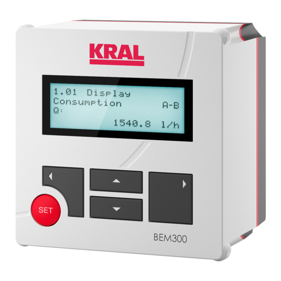
- Page 1 Operating instructions KRAL display and processing unit BEM 300 SW 2.004 OIE 15en-GB Edition 2020-03 Original instructions www.kral.at...
-
Page 2: Table Of Contents
Table of contents 1 About this document ............. 3 10 Operation................ 17 General information ............ 3 10.1 Abbreviations, units and signals ........ 17 10.1.1 Abbreviations........... 17 Target groups .............. 3 10.1.2 Units .............. 17 Associated documents .......... 3 10.1.3 Pulse signals ........... 17 Symbols................. 3 10.2 Key assignment ............ 18 1.4.1 Danger levels ............ 3 10.3 Operation at a glance........... 18... -
Page 3: About This Document
1 About this document 1.1 General information 1 About this document 1.1 General information These instructions form part of the product and must be kept for future reference. Furthermore please observe the associated documents. Notice In these operating instructions the designation "Electronic unit" is used for the "Display and processing unit". -
Page 4: Danger Signs
Cross-reference 2 Safety 2.1 Proper use o The electronic unit is provided for usage with a KRAL flowmeter. o Use the electronic unit only within the operating limits specified in the "Technical data" chapter. 2.2 Foreseeable misuse o Any use that extends beyond the proper use or any other use is misuse. -
Page 5: Technical Data
3 Technical data 3.1 Dimensional drawing 3 Technical data 3.1 Dimensional drawing Fig. 1: Dimensional drawing Parameter Unit Value H x W x D [mm] 145 x 145 x 118 Tab. 2: Dimensions 3.2 Display Criterion Data Text display 4 lines/20 characters Updating rate 100 ms Background illumination 20 levels, can be adjusted via software or analog... -
Page 6: Pulse Input And Analog Input
3 Technical data 3.3 Connection data 3.3.3 Pulse input and analog input Component Designation Unit Value Pulse input Limit frequency min. - max. [Hz] 0.5 – 20000 Power supply for pick up NPN/PNP [V DC] Namur Input impedance NPN/PNP [kΩ] Namur [kΩ] Can be configured for counter mode or encoder mode Analog input Input resistance [kΩ]... -
Page 7: Connection Field
3 Technical data 3.4 Connection field 3.4 Connection field Fig. 2: Termination panel electronic unit Power supply (24 V DC) Pick up 1 Analog output (4 - 20 mA) Pick up 2 Analog output (0 – 10 V) Analog input (0 – 10 V)background illumination Serial interface (RS 232) Pulse output Modbus interface (RS 485) The Modbus connection takes place via terminals. The assignment of the terminals is shown in the wir- ing diagram. -
Page 8: Ambient Conditions
4.1 Functional principle 4.1.1 Usage The electronic unit is provided for usage with a KRAL flowmeter. Flowmeters generate a specific number of pulses per flow volume unit - depending on the size and working point. This device-specific characteristic is called the K-factor (unit: pulses/liter) and is spe- cified on the calibration certificate. -
Page 9: Volume Measurement
Single-line measurement Extension stage Components Functions o 1 flowmeter o Electronic evaluation o 1 pick up o Volume measurement o 1 BEM 300 electronic unit o 1 analog output o 1 pulse output 000135 Basic Operating instructions OIE 15en-GB Edition 2020-03... -
Page 10: Flow Direction Detection
Basic + temperature compensation o Filling o 1 flowmeter o Electronic evaluation o 2 pick ups o Volume measurement o 1 BEM 300 electronic unit o Flow direction detection o 1 analog output o 1 pulse output 000137 Basic + flow direction detection... - Page 11 4 Function description 4.2 Modbus interface Extension stage Components Functions o 2 flowmeters o Electronic evaluation o 2 pick up each o Differential measurement o 1 temperature sensor Pt100 o Flow direction detection o Mass flow measurement each o 1 BEM 500 electronic unit o Temperature compensation o 2 relay outputs 000142...
-
Page 12: Transportation, Storage
Password o Work sheet o Mounting frame with screws and wedge lock washers o Terminal tool o KRAL tool set 5.2 Unpacking and checking the state of delivery o Trained personnel Personnel qualification: Upon delivery check the product for damage during transportation. -
Page 13: Mounting The Electronic Unit To The Wall
6.3 Mounting the electronic unit to the wall o Electrician Personnel qualification: Personal protective equipment: o Work clothing o KRAL tool set Aids: For wall mounting a universal mount is available as an accessory Ä Accessories, Page 26. Electronic unit Universal mount Requirement: ü... -
Page 14: Connection
7.2 Connecting cables to the tension spring terminals o Electrician Personnel qualification: Personal protective equipment: o Work clothing o KRAL tool set Aids: o Diagonal cutter Requirement: ü Cable shortened to correct length ü All wires stripped to approx. 5 mm Remove the rear device cover 1 and remove the terminal tool 2. -
Page 15: Connecting The Pick Up
Replace the rear device cover 1. 7.3 Connecting the pick up o Electrician Personnel qualification: o Work clothing Personal protective equipment: o KRAL tool set Aids: o Diagonal cutter o Wiring diagram ATTENTION Device damage through incorrect connection ► Observe pin assignment and connection data of the electronic unit Ä Technical data, Page 5. -
Page 16: Connecting The Power Supply
Replace the rear device cover. 7.5 Connecting the power supply o Electrician Personnel qualification: Personal protective equipment: o Work clothing o KRAL tool set Aids: o Diagonal cutter o Wiring diagram ATTENTION Device damage through incorrect connection ► Observe pin assignment and connection data of the electronic unit Ä Technical data, Page 5. -
Page 17: Decommissioning
9 Decommissioning 9.1 Taking the electronic unit out of operation Test Procedure Function test Electronic unit: Switch on the power supply. ð The start message is displayed on the display unit. ð The following is displayed no later than 3 seconds: 1.01 Display Volumeter A. -
Page 18: Key Assignment
10 Operation 10.2 Key assignment 10.2 Key assignment The electronic unit is operated by means of five keys. Button Function o Confirm the entry o Reset the total values o Confirm the selection o Switch to the following menu item o Select the previous unit o Increase the digit o Switch to the previous menu item... - Page 19 10 Operation 10.3 Operation at a glance Operating steps Change the value Requirement: 2.01 Setting Enable Password Set to No . Press . ð Flashing cursor indicates the active input field. With change the position within the number input. With increase or decrease the digits. Repeat Steps 2 and 3 for all the digits.
-
Page 20: Menu Description
11 Menu description 11.1 Start Operating steps Call up help, see Call up menu item 1.12 Help Press + simultaneously. operation Navigate Browse with Press to exit the help. 11 Menu description 11.1 Start Menu item Description 1.04 Information = Start message with display of the serial number as well as version of the software and hardware. After switching on the start message shows for three seconds that the electronic unit is ready to oper- ate. -
Page 21: Menu 1: Display
11 Menu description 11.4 Menu 1: Display Menu item Description 0.09 Pulse output pulse This function is only possible after entry of the system password 1919 2.01 Setting Enable width setting Password . Increasing the pulse width always involves a reduction in the maximum output frequency (e.g. pulse width 200 ms – maximum frequency 2.5 Hz). - Page 22 11 Menu description 11.5 Menu 2: General settings Menu item Description 2.02 Setting Select Unit Setting unit rate Rate 2.03 Setting Select Unit Setting unit total Total 2.04 Setting Select Unit Set unit density Density 2.05 Setting Function Setting analog output Analog Output o 1 output 4 – 20 mA o 1 output 0 – 10 V 2.06 Setting Scale The scale of the analog output is used to set the maximum value.
-
Page 23: Menu 3: K-Factors Flowmeter A
11 Menu description 11.6 Menu 3: K-factors flowmeter A Menu item Description 2.12 Setting Averaging The averaging allows for a stable display with varying flow amounts. Possible values, adjusted to the Display Rate Average requirements, are between 1 and 10000. In case of averaging the display of quick changes takes place with a time delay. -
Page 24: Maintenance
12 Maintenance 12.1 Required maintenance 12 Maintenance 12.1 Required maintenance The electronic unit is maintenance-free. 12.2 Cleaning the electronic unit ATTENTION Device damage through water. ► Ensure that no water enters the electronic unit. Wipe the housing with a soft cloth. In the case of strong soiling wipe off the housing surface slightly moist with a common detergent. - Page 25 14 Troubleshooting 14.1 Fault table Fault display Cause and elimination 7.15 Alarm 14 The temperature range of the electronic unit has been exceeded. Temperature range o Check the electronic unit. electronics exceeded. o Replace the electronic unit. 7.16 Alarm 15 Unit The unit of density has been changed. o Convert the numerical value and correct the density value.
-
Page 26: Accessories
15 Accessories 15.1 Installation Further faults Cause and elimination Overflow of the total After an overflow of the total value the electronic unit displays the following: value o For 3 decimal places: ±1 999 999,999 o For 1 decimal place: ±199 999 999,9 o Specify another unit for Total, e.g. m instead of l. -
Page 27: Fixing Kit For Pipe Mounting/Mounting On Omg
Change BEM 4U to BEM 500 Notice The previously used temperature sensors have to be replaced by temperature sensors with Pt100 out- put. These temperature sensors are available from KRAL. During conversion, observe setting the tem- perature sensor units. Notice Depending on the sheeting thickness of the control cabinet the supplied screws may have to be re- placed by longer screws. -
Page 28: Electrical Connection
15 Accessories 15.2 Electrical connection Electronic unit Sheeting** Front frame* Sealing frame* Sheeting bonded to seal** Screws and wedge lock washers* Control cabinet Included in the scope of delivery of the Adapter set BEM 300/BEM 500 Remove the BEM 4U. Slide the front frame 2 and sheeting with seal 3 from the rear onto the electronic unit 1. Position the electronic unit in the control cabinet section. - Page 29 15 Accessories 15.2 Electrical connection Component Parameter Unit Value Output Output voltage [V DC] 24 Output current max. [mA] Output power Function display LED at front panel Current limitation Fold-back, set to approx. 1.05 x I System deviation at load change stat. 10 – 90 % System deviation at load change dyn.
-
Page 30: Plug-In Power Supply Unit Een 13
Ratio of mass-to-volume (e.g. kg/m o Describes the relationship of density-to-temperature Density table o Only contains one fixed density value for BEM 300 Differential measurement o The values of two flowmeters are measured and subtracted o Amount flowing per time unit (e.g. l/s) - Page 31 16 Appendix 16.1 Glossary Designation Meaning o Time span after whose expiry the output is identical with the input Adjusting time Single-line measurement o The values of a flowmeter are measured and evaluated o Display and processing unit BEM 300/BEM 500 Electronic unit o Display and processing unit BEM 100/BEM 150 Galvanic isolation o Isolation of differing voltage potentials...
- Page 32 KRAL GmbH, 6890 Lustenau, Austria, Tel.: +43/5577/86644-0, E-Mail: kral@kral.at www.kral.at...
Need help?
Do you have a question about the BEM 300 and is the answer not in the manual?
Questions and answers