
Related Manuals for KRAL OMP Series


Summary of Contents for KRAL OMP Series
- Page 1 Operating Instructions KRAL Flowmeter. OMP Series OIO 23en Edition 10/2017 Original instructions www.kral.at...
-
Page 2: Table Of Contents
Table of contents About this document Installation, removal and connection □ □ General information Safety instructions for installation and removal □ □ Target groups Installing the flowmeter ▪ Installation types □ Symbols ▪ Preferred installation variant □ Danger levels ▪ Recommendations for alternative installation □... -
Page 3: Target Groups
General information General information About this document The operating instructions form part of the KRAL flowmeter and must be kept for future reference. Furthermore please observe the associated documents. Target groups Target group Tasks □ Operator-owner Keep these instructions available at the system site for future reference. -
Page 4: Danger Levels
Danger levels Danger levels Warning Danger level Consequences of non-observances Danger Immediate threat of danger Serious personal injury, death Warning Possible threat of danger Serious personal injury, invalidity Caution Potentially dangerous situation Slight personal injury Caution Potentially dangerous situation Material damage Associated documents Calibration certificate Declaration of conformity according to EU Directive 2006/42/EC... -
Page 5: Proper Use
Proper use Safety □ Use flowmeters of the OMP series solely for flow measurement of lubricating liquids that are chemically neutral and do not contain any gas or solids content. □ Flowmeters require the operation with clean liquids. If coarse soiling, solid particles in the liquid or abrasive fine particles occur during operation, the flowmeter has to be protected additionally by a correspondingly dimensioned operating filter in the pipe system, see "Cleaning the pipe system",... -
Page 6: Type Code
Type code Type code Identification 1 Series 2 Size 3 Sensor technology 4 Function of sensor technology OMP-020.FDBAAD.0001 5 Material of bearing 6 Material of seal 7 Mechanical connection 8 Electrical connection 9 Version index Fig. 1 Type code Item Designation Description Series... -
Page 7: Rating Plate
Rating plate Rating plate 1 Serial number 2 Year of construction 3 K-factor 4 Preferred flow direction 5 Maximum temperature 6 Type ® 7 Maximum pressure Fig. 2 Rating plate Operating Instructions OIO 23en Edition 10/2017... -
Page 8: Load Due To Pressure Pulsation
Operating limits Operating limits Technical data The values specified on the rating plate and the calibration certificate apply. The permissible operational limits of individual values influence each other so that every application is checked individually by the manufacturer when selecting the flowmeter. If no operating data are provided by the orderer, standardized substitute operating data are used. -
Page 9: Substitute Operating Data
The sound pressure level of the flowmeter amounts to less than 70 dB(A). Heating system A heating system is not installed at the factory. The customer can optionally fit OMP-series KRAL flowmeters with a trace heating system. The manufacturer recommends heating systems for high- viscosity liquids that do not flow sufficiently if not heated, because bearing damage and destruction of the device may otherwise result. -
Page 10: Dimensions And Weights
Dimensions and weights CAUTION Defective pick up, temperature sensor or cabling due to exceeding of the maximum temperature. ► Do not heat the pick up, temperature sensor, junction box and corresponding cables above the temperature specified in the associated operating instructions. ►... -
Page 11: Omp With Din Flange
Dimensions and weights OMP with DIN flange G1/4" M16x1 / M18x1 Nominal diameter flange M16x1/ Pick up hole/ M18x1 Mounting connection element G1/4" Temperature sensor hole Outer diameter Total length Flowmeter length without connections L3, L4 Flange thickness Pitch circle Fig. -
Page 12: Omp With Ansi Flange
Dimensions and weights OMP with ANSI flange G1/4" M16x1 / M18x1 Nominal diameter flange M16x1/ Pick up hole/ M18x1 Mounting connection element G1/4" Temperature sensor hole Outer diameter Total length Flowmeter length without connections L3, L4 Flange thickness Pitch circle Fig. -
Page 13: Omp With Jis Flange
Dimensions and weights OMP with JIS flange Nominal diameter G1/4" M16x1 / M18x1 flange M16x1/ Pick up hole/ M18x1 Mounting connection element G1/4" Temperature sensor hole Outer diameter Total length Flowmeter length without connections L3, L4 Flange thickness Pitch circle Fig. -
Page 14: Load-Bearing Capacity
Load-bearing capacity Load-bearing capacity Load-bearing capacity OMP 13 100000 5000 2000 50000 10000 1000 1000 h 5000 h 10000 h 30000 h 100000 50000 10000 5000 2000 1000 A Short-time operation B Continuous operation C Pressure loss D Flow rate The values apply for lubricating liquids at temperatures of up to 120 °C. -
Page 15: Load-Bearing Capacity Omp
Load-bearing capacity Load-bearing capacity OMP 20 100000 50000 10000 5000 2000 1000 1000 h 5000 h 10000 h 30000 h 100000 50000 10000 2000 1000 5000 10,5 13,5 A Short-time operation B Continuous operation C Pressure loss D Flow rate The values apply for lubricating liquids at temperatures of up to 120 °C. -
Page 16: Load-Bearing Capacity Omp
Load-bearing capacity Load-bearing capacity OMP 32 100000 50000 10000 5000 2000 1000 1000 h 5000 h 10000 h 30000 h 100000 50000 10000 5000 2000 1000 A Short-time operation B Continuous operation C Pressure loss D Flow rate The values apply for lubricating liquids at temperatures of up to 120 °C. Abrasive and aggressive liquids reduce the durability. -
Page 17: Load-Bearing Capacity Omp
Load-bearing capacity Load-bearing capacity OMP 52 100000 50000 10000 5000 2000 1000 1000 h 5000 h 10000 h 30000 h 100000 50000 1000 10000 5000 2000 17,5 52,5 87,5 122,5 157,5 A Short-time operation B Continuous operation C Pressure loss D Flow rate The values apply for lubricating liquids at temperatures of up to 120 °C. -
Page 18: Description
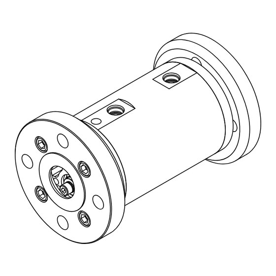
Description Description Function description Fig. 1 Structure, flowmeter OMP series 1 Connection 6 Measuring screw small 2* Bearing cover 7 Ball bearing, floating bearing end 3 Temperature sensor hole 8 Measuring screw large 4 Pick up hole 9 Ball bearing, fixed bearing end... -
Page 19: Signal Generation
- require the use of a second pick up. This additional signal (90° phase-offset) and the incremental encoding inputs available in the KRAL electronic unit can be used to determine the direction of flow and to take it into consideration when calculating the total values. -
Page 20: Lifting The Flowmeter
Unpacking and checking the state of delivery Unpacking and checking the state of delivery Transportation, storage and disposal 1. Upon delivery unpack the flowmeter and check for transport damage. 2. Report damage during transportation immediately to the manufacturer. 3. Store the supplied pick up and temperature sensor for the installation. 4. -
Page 21: Removing The Preservation
Disposal After about six months storage check the oil level in the flowmeter and if necessary top up oil. Check the preservation of the outer housing and if necessary apply oil to the parts again. Notice: Store the preserved flowmeter cool and dry and protect it against direct sunlight. Notice: After a longer storage time the manufacturer recommends that you have the flowmeter recalibrated, see "Re-calibration of the flowmeters", page 29. -
Page 22: Installing The Flowmeter
"Trace heating system", page 9. Installing the flowmeter Flowmeters of the OMP series can be operated in any mounting position. Notice: Both directions of flow are possible. The preferred flow direction is indicated on the rating plate by means of a bright arrow, see Fig. -
Page 23: Preferred Installation Variant
Installing the flowmeter Preferred installation variant Flow vertically from bottom to top ► Preferred installation variant. Recommendations for alternative installation variants Flow vertically from top to bottom No vertical installation with open outlet ► Ensure that the liquid does not flow freely out ►... -
Page 24: Protect The Flowmeter Against Soiling
Installing the flowmeter CAUTION Measuring error through air in the pipe system and/or incorrect installation of the flowmeter. ► In the case of horizontal installation of the flowmeter at the highest point of the pipe system an air pocket can arise that results in measuring errors. ►... -
Page 25: Electrical Installation
Electrical installation 1. Remove the protective covers and store them. 2. Install the flowmeter stress-free in the pipe system while taking the preferred direction of flow into account and ensure that the connections of the pick up remain accessible. 3. The screw-in length of the piping may not exceed the threaded length of the flowmeter, since the flow cross-section is narrowed and internal components can be damaged. - Page 26 Removing the flowmeter WARNING Risk of injury through emitted hot, poisonous or corrosive pumped liquid when removing the flowmeter. ► Observe the safety regulations for handling dangerous liquids. ► Ensure that the flowmeter is not under pressure. ► Collect the emitted pumped liquid safely and dispose of it in an environmentally compatible manner.
-
Page 27: Cleaning The Pipe System
Commissioning Commissioning Operation Cleaning the pipe system To protect the flowmeter against soiling carefully clean the complete pipe system before commissioning. Possibilities: □ Rinsing via bypass □ Rinsing with flowmeter CAUTION Damage to equipment through usage of an incorrect rinsing liquid. ►... -
Page 28: Switching Off The Flowmeter
Switching off the flowmeter CAUTION Measuring error through gas inclusion in the pipe system. ► Before commissioning, make sure that the flowmeter is filled. ► Vent the pipe system. CAUTION Increased wear and/or blocking of the flowmeter due to solid particles or abrasive fine particles in the liquid. -
Page 29: Safety Instructions On Repairs
Safety instructions on repairs Safety instructions on repairs Maintenance The following safety instructions must be observed during all the repair work: ► All the work may only be carried out by authorized qualified personnel. ► Wear protective clothing during all the work. ►... - Page 30 Mounting instructions OMP 13 Mounting instructions OMP 13 115.1 115.1 739.1 915.5 115.2 Fig. 3 Fig. 1 Fig. 2 817.4 672.2 817.3 817.2 672.1 817.1 Fig. 5 Fig. 4 Distance sleeve 739.1 O-ring 915.5 Socket screw 115.1 Flange 739.2 O-ring 115.2 Flange 817.1 Deep-groove ball bearing...
-
Page 31: Removing Seals And Bearings
Mounting instructions OMP 13 Removing seals and bearings Prerequisites: □ Flowmeter removed from system □ Pick up insert removed 1. Remove the socket screws 915.5 and the flanges 115.1 and 115.2, see Fig. 1, page 30. 2. Remove the O-rings 739.1 and 739.2, see Fig. 2, page 30. 3. -
Page 32: Mounting Instructions Omp 20/32
Mounting instructions OMP 20/32 Mounting instructions OMP 20/32 739.2 115.1 115.1 915.1 915.2 739.1 115.2 Fig. 8 Fig. 6 Fig. 7 869.4 817.4 672.2 817.3 904.2 Fig. 9 064.2 915.7 869.2 817.2 672.1 817.1 904.1 064.1 915.6 Fig. 11 Fig. 10 Distance sleeve 739.1 O-ring 904.1 Wedge lock washer... -
Page 33: Removing Seals And Bearings
Mounting instructions OMP 20/32 Removing seals and bearings Prerequisites: □ Flowmeter removed from system □ Pick up insert removed 1. Remove the socket screws 915.1 and 915.2, flanges 115.1 and 115.2, see Fig. 6, page 32. 2. Remove the O-rings 739.1 and 739.2, see Fig. 7, page 32. 3. -
Page 34: Mounting Instructions Omp 52
Mounting instructions OMP 52 Mounting instructions OMP 52 080.2 739.3 915.4 739.4 080.1 739.3 080.1 915.3 115.2 115.1 915.1 915.2 739.2 739.1 Fig. 12 Fig. 13 064.2 904.2 915.7 904.1 080.1 064.1 915.6 057.2 057.1 Fig. 14 Fig. 15 Fig. 16 672.2 818.2 057.2... -
Page 35: Removing Seals And Bearings
Mounting instructions OMP 52 Fig. 18 Fig. 19 Spacer 739.1 O-ring 868.2 Support ring 57.1 Threaded ring 739.2 O-ring (inlet) 868.4 Support ring 057.2 Threaded ring 739.3 O-ring 869.2 Circlip 064.1 Supporting ring 739.4 O-ring (inlet) 869.4 Circlip 064.2 Supporting ring 817.1 Deep-groove ball 904.1... -
Page 36: Installing Seals And Bearings
Mounting instructions OMP 52 Installing seals and bearings Prerequisites: □ Replacement parts available □ Loctite 242 1. Insert the O-ring 739.3 and 739.4 into the bearing cover 080.1 and 080.2. 2. Press the ball bearings 818.1 and 818.2 into the bearing cover 080.1. Notice: Press the angular-contact ball bearings on in face-to-face arrangement, see Fig. -
Page 37: Troubleshooting
Possible faults Faults can have different causes. The following tables list the symptoms of a fault, the possible causes Troubleshooting and measures for troubleshooting. Possible faults Fault Cause/Remedy □ Flowmeter leaks 1, 2, 6 □ No flow rate 3, 7, 8, 20, 22, 23 □... - Page 38 Troubleshooting Cause Remedy Flow rate fluctuations too high ► Ensure a continuous flow rate by taking suitable measures (use of a different pump. valve, damper, etc.). - or - ► Smoothen the indication, while observing the electronic operating instructions. Filling amount too low ►...
-
Page 39: Maintenance Kits
Spare parts Spare parts Appendix Maintenance kits Notice: The maintenance kits contain only the numbered parts and are only supplied complete. 739.2 739.5 597.1 869.4 817.4 817.3 739.1 869.2 817.2 817.1 Fig. 1 Maintenance kit OMP 13 Qty. Item No. Part Qty. - Page 40 Spare parts 739.2 739.5 597.1 869.4 817.4 817.3 739.1 869.2 817.2 817.1 Fig. 2 Maintenance kit OMP 20/32 739.2 739.5 597.1 869.4 817.4 817.3 739.1 869.2 817.2 817.1 Fig. 3 Maintenance kit OMP 20/32 – high temperature Qty. Item No. Part Qty.
- Page 41 Spare parts 739.2 739.1 739.5 597.1 739.4 739.3 869.4 817.2 818.2 869.2 817.1 818.1 Fig. 4 Maintenance kit OMP 52 739.2 739.1 739.5 739.4 597.1 739.3 869.4 817.2 818.2 869.2 817.1 818.1 Fig. 5 Maintenance kit OMP 52 – high temperature Operating Instructions OIO 23en Edition 10/2017...
-
Page 42: Accessories
Accessories Qty. Item No. Part Qty. Item No. Part 597.1 Screw plug 817.2 Deep-groove ball bearing 739.1 O-ring 818.1 Angular-contact ball bearings 739.2 O-ring 818.2 Angular-contact ball bearings 739.3 O-ring 869.2 Circlip 739.4 O-ring 869.4 Circlip 739.5 O-ring 870.1 Circlip 817.1 Deep-groove ball bearing 870.2... - Page 43 As an option the manufacturer offers a junction box that facilitates the electrical connection of the various sensors for the flowmeters of the OMP series. Up to three sensors can be connected. The sensor cables are combined to form a multi-strand connecting cable which can be supplied as well optionally if required.
-
Page 44: Mounting The Junction Box
Accessories Mounting the junction box Mounting the junction box on OMP 13 - 52 1 Cable pick up and temperature sensor 2 Connector pick up 3 Hexagon pick up 4 Washer junction box 5 Pick up inserts 6 Base plate junction box Fig. -
Page 45: Connecting The Junction Box
Accessories Mounting the junction box for OMP 13 - 52 high temperature 1 Fastening angle 2 Hexagon nut amplifier 3 Amplifier 4 Cable temperature sensor and pick up 5 Pick up insert Fig. 11 Example OMP 32 1. Disconnect the cables 4 of the pick ups with amplifier and the temperature sensor. Ensure that the cable length is sufficient. -
Page 46: Connecting The Extension Cable
Accessories 1. Dismantle the junction box lid 1. 2. Carry out the cabling of the pick up and of the temperature sensor through the cable glands 2 in the junction box. Observe the connection circuit diagram, see Fig. 7, page 42. 3. -
Page 47: Tightening Torques
Tightening torques Tightening torques Tightening torque [Nm] for screws with metric threads + head contact surfaces With thread measured in inches + wedge lock Stainless steel Screw plugs with washers screws A2 and A4 elastomer seal Rust- 8.8 + proof 10.9 Alu* A4-70... - Page 48 KRAL AG, Bildgasse 40, Industrie Nord, 6890 Lustenau, Austria,Tel.: +43 / 55 77 / 8 66 44 - 0 Fax: +43 / 55 77 / 8 84 33, www.kral.at, E-Mail: kral@kral.at KRAL AG, 6890 Lustenau, Austria, Tel.: +43 / 55 77 / 8 66 44 - 0, E-Mail: kral@kral.at...
Need help?
Do you have a question about the OMP Series and is the answer not in the manual?
Questions and answers
como se conecta la salida de pulsos