
Related Manuals for KRAL BEM 100


Summary of Contents for KRAL BEM 100
- Page 1 Operating instructions KRAL processing unit BEM 100 SW 1.06 OIE 26en-GB Edition 2021-08 Original instructions www.kral.at...
-
Page 2: Table Of Contents
Table of contents 1 About this document ............. 3 9.1.1 Setting the Modbus address...... 16 9.1.2 Managing the density table...... 16 Target groups .............. 3 9.1.3 Entering the density table ........ 17 Associated documents .......... 3 9.1.4 Selecting the mode for volume measurement Symbols................. 3 ................. 18 1.3.1 Danger levels ............ 3 9.1.5... -
Page 3: About This Document
1 About this document 1.1 Target groups 1 About this document 1.1 Target groups The instructions are intended for the following persons: o Persons who work with the product o Operator-owners who are responsible for the use of the product Persons who work with the product must be qualified. -
Page 4: Symbols In This Document
2 Safety 2.1 Proper use 1.3.3 Symbols in this document Meaning Warning personal injury Safety instruction Request for action Multi-step instructions for actions Action result Cross-reference 2 Safety 2.1 Proper use Use the processing unit only within the operating limits specified in the chapter "Technical data". 2.2 Foreseeable misuse o Any use that extends beyond the proper use or any other use is misuse. -
Page 5: Technical Data
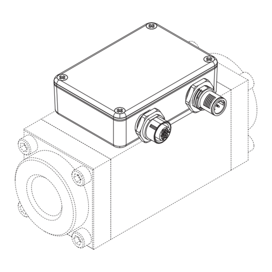
4 Technical data 4.1 Ambient conditions 4 Technical data 4.1 Ambient conditions Parameter Unit Value min. Value max. Storage temperature [°C] +105 Operating temperature [°C] +105 Humidity relative (not condensing) Vibration (@ 20 mm/s, ± 1.0 g max.) [Hz] Degree of protection IP 67 Tab. 2: Ambient conditions 4.2 Dimensional drawing... -
Page 6: Modbus Interface
5.1 Functional principle 5.1.1 Usage The processing unit is intended for usage with a KRAL flowmeter of the OME Compact series and is mounted directly on the flowmeter. Flowmeters generate a specific number of pulses per flow volume unit – depending on the size and working point. -
Page 7: Volume Measurement
5 Function description 5.1 Functional principle Fig. 4: Connecting several processing units Flowmeter with processing unit Display device (HMI) Flowmeter with processing unit Power supply display device Flowmeter with processing unit C1 Power supply processing unit Terminating resistor C2 Connection Modbus RS-485 Up to 32 processing units can be connected (32 sensor evaluations electrically in parallel). -
Page 8: Modbus Communication
5 Function description 5.2 Modbus communication 5.2 Modbus communication 5.2.1 Supported Modbus functions Code Modbus function Register Application examples READ HOLDING REGISTERS 4xxxx - Reading out of measured values, counter statuses, average values - Reading out of the device configuration PRESET MULTIPLE REGISTERS 4xxxx - Device programming Tab. 8: Modbus functions... -
Page 9: Automatically Updated Parameters
5 Function description 5.2 Modbus communication 5.2.5 Automatically updated parameters These parameters are automatically updated by the processing unit 16 times per second, meaning that the updating interval for the Modbus data amounts to 62.5 ms. Name Description Address Type Length Alarm_Read Error message 0x14 Hold_Timer... -
Page 10: K-Factor Table
5 Function description 5.2 Modbus communication Name Description Address Type Length DEC Value range Density_Reference_2 Density of heavy fuel oil at 15 °C [kg/m 0x3E 0.1 ... 80000.0 (Density_Determination = 3, 4 or 5) Maintenance_Hours Number of operating hours until the required 0x4A –... -
Page 11: Density Tables
5 Function description 5.2 Modbus communication 5.2.8 Density tables Name Description Address Type Length DEC Value range Temperature 1.1 Temperature 1 [°C] 0x60 -40.0 ... +200.0 Temperature 1.2 Temperature 2 [°C] 0x61 -40.0 ... +200.0 Temperature 1.3 Temperature 3 [°C] 0x62 -40.0 ... -
Page 12: Error Messages
5 Function description 5.2 Modbus communication 5.2.9 Error messages Mask Error message Description 0x00000001 Alarm 1 – K-factor table: Frequencies not in The frequency values in the K-factor table are not all ascending order in ascending order. 0x00000002 Alarm 2 – Density table: Temperatures not in The temperature values in one of the density tables ascending order are not all in ascending order. -
Page 13: Parameter For Clearing Error Messages
6 Transportation, storage 6.1 Unpacking and checking the state of delivery 5.2.10 Parameter for clearing error messages This parameter can only be written by the user. Name Description Address Type Length Alarm_Clear Clearing of an error message from the 0xC4 parameter "Alarm_Read"... -
Page 14: Installation, Removal
7 Installation, removal 7.1 Dangers during installation, removal 7 Installation, removal 7.1 Dangers during installation, removal The following safety instructions must be strictly observed: o Have all work only carried out by electricians. o Do not take apart the electronic unit. 7.2 Installing the processing unit One processing unit is assigned to exactly one flowmeter. - Page 15 8 Connection 8.2 Connecting the processing unit Fig. 6: Connecting one processing unit Fig. 7: Connecting several processing units Flowmeter with processing unit Display device (HMI) Flowmeter with processing unit Power supply display device Flowmeter with processing unit C1 Power supply processing unit Terminating resistor C2 Connection Modbus RS-485 Requirement:...
-
Page 16: Operation
9 Operation 9.1 Carrying out the basic settings 9 Operation 9.1 Carrying out the basic settings 9.1.1 Setting the Modbus address Modbus addressing is effected by means of two address selector switches on the circuit board of the processing unit. Fig. 8: Modbus addressing Remove the cover of the processing unit. -
Page 17: Entering The Density Table
9 Operation 9.1 Carrying out the basic settings Entering density values manually Density values and temperature values can be entered manually. Set the parameter "Density_Determination" to 0, 1 or 2 and enter density values. Having density values calculated In the case of fuel oils the temperature-dependent density values can be calculated automatically from a reference value. -
Page 18: Selecting The Mode For Volume Measurement
9 Operation 9.1 Carrying out the basic settings 9.1.4 Selecting the mode for volume measurement The parameter "Flow_Metering_Mode" is used to control the form in which the processing unit outputs the measured volumes. Three modes are available. Value Description Pure measured value, without correction Measured value with temperature compensation Measured value converted into mass [kg] Tab. 23: Parameter "Flow_Metering_Mode"... -
Page 19: Specifying The Maximum Flow Rate
9 Operation 9.2 Reading the measured values and status information 9.1.8 Specifying the maximum flow rate The maximum flow rate in [l/h] is specified by using the parameter "Maximum_Flow_Rate". If the cur- rent flow rate exceeds the value specified in the parameter, an error message is output, see "Alarm 29". -
Page 20: Clearing Error Messages
10 Maintenance 10.1 Required maintenance 9.2.2 Clearing error messages Error messages are stored in the parameter "Alarm_Read". Individual, several or all the error messages can be cleared. The parameter "Alarm_Clear" is used to clear error messages. The parameter has to be written with the mask assigned to the error message. -
Page 21: Disposal
11 Disposal 11.1 Disposing of the electronic unit 11 Disposal 11.1 Disposing of the electronic unit ATTENTION Environmental damage through improper disposal. ► Dispose of all the components in an environmentally friendly manner in accordance with the applic- able local regulations. As electronic waste the electronic unit has to be disposed of properly. -
Page 22: Error Tree: No Communication
12 Troubleshooting 12.3 Error tree: No communication 12.3 Error tree: No communication Remove the cover of the processing unit and check the status of the LEDs. Power supply: 1. Check the power supply (12-24 VDC). Does green LED 8 light up? Temperature exceeds 105 °C: Overheating: 1. -
Page 23: Error Tree: No Flow
12 Troubleshooting 12.4 Error tree: No flow 12.4 Error tree: No flow Remove the cover of the processing unit and check the status of the LEDs. 1. Check the cabling of the pick ups. - Counter mode: Does red LED 1 or 2 flash? 2. - Page 24 KRAL GmbH, 6890 Lustenau, Austria, Tel.: +43/5577/86644-0, E-Mail: kral@kral.at www.kral.at...
Need help?
Do you have a question about the BEM 100 and is the answer not in the manual?
Questions and answers