
Subscribe to Our Youtube Channel
Related Manuals for KRAL BEM 500 Series


Summary of Contents for KRAL BEM 500 Series
- Page 1 Operating Instructions KRAL Electronics. Series BEM 500 OIE 12en HW 3.003/SW 3.004 Edition 2019-02 www.kral.at...
-
Page 2: Table Of Contents
Electronic evaluation ▪ Safety instructions for electrical □ Bus connection installation □ ▪ Connecting cables to the tension Applications of the KRAL electronic unit spring terminals ▪ Single-line measurement ▪ Connect the pick ups and temperature ▪ Differential measurement sensors ▪... - Page 3 Table of content □ □ Menu 1: Display Menu 5: K-factors Volumeter B ▪ ▪ 1.01 Consumption 5.01 Volumeter B Point 1 ▪ 1.02 Total with reset □ ▪ 1.03 Volumeter A Menu 6: Density table 1/ ▪ 1.04 Volumeter A Total with reset Density determination ▪...
-
Page 4: Target Groups
Action steps installation and removal Action steps electrical installation Check or fault table Operating steps for electronic unit Faults in the electronic unit Faults in the KRAL Volumeter Faults in the plant Input errors Request for action OIE 12en Edition 2019-02... -
Page 5: Danger Levels
Danger levels Danger levels Warning Danger level Consequences of non-observances Danger Immediate threat of danger Serious personal injury, death Warning Possible threat of danger Serious personal injury, invalidity Caution Potentially dangerous situation Slight personal injury Caution Potentially dangerous situation Material damage Associated documents Declaration of conformity as per EU Directive 2014/30/EU and 2014/35/EU Corresponding operating instructions for the Volumeter... -
Page 6: Volume Measurement
Volume measurement With its functional scope the KRAL electronic unit covers a wide range of functions. The electronic unit is Function description optimized for use together with KRAL Volumeters. KRAL Volumeters generate a specific number of pulses per flow volume unit - depending on the size and working point. This device-specific characteristic is called the K-factor (unit: Pulse/Liter) and can be found on the enclosed calibration certificate. -
Page 7: Temperature Compensation
For the case of operation with different fluids two different density tables can be entered and selected. Differential measurement The KRAL electronic unit can process the signals of two volumeters and determine and display the links possible with it. □... -
Page 8: Flow Direction Detection
Batching A simple filling function can be implemented with the KRAL electronic unit, see "1.07 Batch quantity", Page 35. After the filling function has been started, Relay output 1 is activated when the specified quantity is reached in order, for example, to close a valve that interrupts the filling process, see "3.13 Function relay 1", Page 42. -
Page 9: Applications Of The Kral Electronic Unit
Applications of the KRAL electronic unit Applications of the KRAL electronic unit Different extension stages of the electronic unit are presented on the basis of the following examples. This allows the required functional scope to be selected in accordance with the requirements. -
Page 10: Differential Measurement
Applications of the KRAL electronic unit Differential measurement Extension stage Components Functions □ □ 2 Volumeters Electronic evaluation □ □ 1 Pick up each Differential measurement □ □ 1 BEM 500 electronic unit 2 Relay outputs □ 2 Analog outputs □... -
Page 11: Unpacking And Checking The State Of Delivery
Unpacking and checking the state of delivery Unpacking and checking the state of delivery Transportation, storage and maintenance 1. On delivery unpack the electronic unit and check for damage during transportation. 2. Report damage during transportation immediately to the manufacturer. 3. -
Page 12: Safety Instructions On Installation, Removal And Connection
The following components belong to the scope of delivery of the electronic unit: □ Operating instructions □ Password □ Work sheet □ Mounting frame incl. screws and lock washers □ Terminal tool □ KRAL tool set OIE 12en Edition 2019-02 Operating Instructions... -
Page 13: Installation In The Control Cabinet
BEM 4U to BEM 300/500", page 55. Required minimum mounting depth: 80 mm Dimensions of front frame: □ Height: 145 mm □ Width: 145 mm □ Depth: 12 mm Aids: □ KRAL tool set Operating Instructions OIE 12en Edition 2019-02... -
Page 14: Wall Mounting
All cables have been cut to length and connected Aids □ KRAL tool set 1. Slide the electronic unit 1 into the universal mount 2. 2. Fasten the electronic unit using the supplied screws, washers and wedge lock washers. The electronic unit is ready to operate after the power supply has been switched on. -
Page 15: Removal
Removal Fig. 5 Fixing kit for pipe mounting / Fig. 6 Fixing kit for KRAL Volumeter KRAL Volumeter OMG series OME series 1 Electronic unit 1 Electronic unit 2 Universal mount 2 Universal mount 3 Fixing kit pipe mounting/OMG 3 Fixing kit OME Prerequisite: □... -
Page 16: Termination Panel Of The Electronic Unit
Termination panel of the electronic unit Termination panel of the electronic unit Technical data 24 VDC RS232 Pulse Output (2) Pulse Output (1) RS485 Pt 100 A Pt 100 B 4...20mA (1) 4...20mA (2) Pulse In A Pulse In B Pick up B 1 Pick up A 1 Pick up A 2... -
Page 17: Technical Data Of Connections
Technical data of connections Technical data of connections Power supply Designation Data □ Power supply Range 24 V DC ± 20% □ Max. current consumption 0.5 A □ Insulation voltage < 500 V Tension spring terminals Cable type Terminating range □... -
Page 18: Display
Technical data of connections Component Data □ Analog outputs 0–10 V Active voltage sources □ Short-circuit proof □ Load > 500 Ω □ Resolution: 1 mV □ Scalable □ Temperature drift: ± 0.1% □ Calibration tolerance: ± 0.1% □ Reaction time: 20 ms x smoothing value □... - Page 19 Technical data of connections The following variables are available at the Modbus: Data Explanation of Data reading command Variable designation value range data value to BEM in HEX 1.01 Consumption rate Q 4000 1...3 +/- 2147483647 Unit rate 0103 4000 0002 D1CB 1.02 Total 1 4002 1...3 +/- 2000000000...
- Page 20 Technical data of connections Value Meaning Value Meaning Value Meaning °C °F Tab. 4 Data values unit temperature Value Meaning 1 decimal place, meaning all values with 1...3 decimal places must be divided by 10 ) to get the actual value. 2 decimal places, meaning all values with 1...3 decimal places must be divided by 100 ) to get the actual value.
-
Page 21: Ambient Conditions
Connection assignments Ambient conditions Criterion Data □ Storage temperature Range -20...+80 °C □ Operating temperature Range -20...+70 °C □ Humidity 97% relative humidity, non-condensing □ EMC emitted interference EN 61326 and immunity to interference □ Vibration EN 60068–2–47 □ EN 60068–2–64 □... -
Page 22: Pulse Outputs
Connection assignments Pulse outputs Connection Function Terminal Pulse output 1 Signal Pulse output 2 Signal The data logger can be connected to these connections, see "Data acquisition accessories", page 59. Relay outputs Connection Function Terminal Relay output 1: NO contact Bypass valve or filling valve Switching contact NC contact... -
Page 23: Safety Instructions For Commissioning
Safety instructions for commissioning Safety instructions for commissioning Commissioning The following safety instructions must be observed during commissioning: □ The following qualifications are required for commissioning: ▪ Practical electrotechnical training ▪ Knowledge of the safety guidelines at the workplace ▪ Knowledge of the electrotechnical safety guidelines Connecting cables Safety instructions for electrical installation... -
Page 24: Connecting Cables To The Tension Spring Terminals
Connecting cables Connecting cables to the tension spring Aids terminals □ KRAL tool set □ Diagonal cutter Prerequisite: □ Cable shortened to correct length □ All wires stripped to approx. 5 mm 1. Remove the rear device cover and remove 4. -
Page 25: Connect The Pick Ups And Temperature Sensors
□ Pick ups for both volumeters are mounted □ Temperature sensors for both volumeters are mounted Aids: □ KRAL tool set □ Diagonal cutter CAUTION Damage to equipment through incorrect connection of temperature inputs (terminals 3–5 and/or 36–38). ► Before connecting the electronic unit to the power supply, ensure that all consumers (temperature sensors, pick ups) are connected correctly, see wiring diagram. -
Page 26: Connecting The Power Supply
Prerequisites: □ All sensors are correctly connected Aids: □ KRAL tool set □ Diagonal cutter CAUTION Damage to equipment through incorrect wiring of consumer inputs. ► Before connecting the electronic unit to the power supply, ensure that all consumers (temperature sensors, pick ups) are connected correctly, see wiring diagram. -
Page 27: Checking The Electronic Unit
Checking the electronic unit Checking the electronic unit Test Procedure Installation ► Check that the electronic unit is seated firmly. ► For wall and pipe mounting as well as mounting on volumeter: ensure that the rear device cover and cable entries seal properly. -
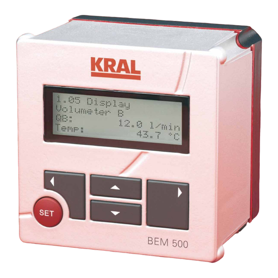
Page 28: Key Assignment
Key assignment Key assignment Operation of the basic functions The electronic unit is operated by means of five keys. Key/combination Designation Function □ Confirmation of the entry □ Resetting of total values □ Confirmation of the selection □ Change to the following page of the menu □... -
Page 29: Operation At A Glance
Operation at a glance Operation at a glance General operating steps The following table describes the input and modification of the password as well as general operating steps, such as the changing of values and units. The password is included in the scope of delivery and consists of four digits. -
Page 30: Operating The Basic Functions
Operation at a glance Operating the basic functions The following table describes the basic operating steps. They can be carried out in part without a password having to be entered. Operating steps Reading the consumption ► Press ARROW UP and ARROW DOWN simultaneously. see "1.01 Consumption", "Consumption "... -
Page 31: Abbreviations, Quantities And Units
Abbreviations, quantities and units Abbreviations, quantities and units Abbreviations used Abbreviation Meaning Current consumption QA-QB Nominal flow rate rated Total consumption since last reset, without password protection Total consumption since last reset, with password protection Current flow Volumeter A (supply line) Current flow Volumeter B (return line) Temp. -
Page 32: Menu Structure
Menu structure Menu structure Menu description Menu Page (information) □ Display 1.00 Information □ 1.01 Consumption □ 1.02 Total □ 1.03 Volumeter A □ 1.04 Volumeter A Total □ 1.05 Volumeter B □ 1.06 Volumeter B Total □ 1.07 Batch quantity □... - Page 33 Menu structure Menu Page (information) □ 3.14 Limit value bypass □ 3.15 Time delay bypass □ 3.16 Waiting period repeat bypass □ 3.17 Relay 1 switch □ 3.18 Relay 2 switch □ 3.19 Address Modbus □ K-factors Volumeter A 4.01 Volumeter A Point 1 □...
-
Page 34: Start
Start Start This page displays brief instructions for operating. Press ARROW UPor ARROW After the power supply has been switched on, a DOWNto navigate in the text. Use SET to exit the start message indicates that the electronic unit is help. -
Page 35: Volumeter A
Menu 1: Display Note: Depending on the number of decimal The "Volumeter A Total" page displays the total places the total value stops at the following value of Volumeter A since the last resetting. minimum or maximum values: Resetting of the value functions analog to menu item 1.02. -
Page 36: Flow Direction Change Volumeter A
Menu 2: General settings 1.08 Flow direction change Volumeter A 1.13 Setting select language 1.13 Setting 1.08 Display Select Direction change Language: Volumeter A: English The language is selected on this page. The page On this page the number of flow direction can be called up via the shortcut, see "1.13 changes of Volumeter A since the last reset is Setting select language", page 34. -
Page 37: Change Password
Menu 2: General settings 2.02 Change password This setting is only effective if "Volume at X°" has been selected under "2.03 Select mode". 2.05 Select unit rate 2.02 Setting Change Password: 2.05 Setting Select Unit Rate: After the valid password has been entered, the l/min password can be changed on this page. -
Page 38: Select Density Determination
Menu 2: General settings 2.09 Select density determination 2.12 Function pick up 2.12 Setting Function 2.09 Setting Pick up: Select density determination: Table 1 The setting of the pick up type has to be adapted to the pick up used. Setting Description Available signals:... -
Page 39: Averaging Display Rate
Menu 2: General settings The threshold value is required for consumption No filter is active for Averaging 0 and 1. In the measurement when the consumer is switched off case of Averaging 2–9 a continuous average- and the circulation pump continues to run. The value generation is carried out. -
Page 40: Maximum Temperature Volumeter
Menu 3: Output settings 2.20 Maximum temperature Volumeter Available values: □ Q Rate consumption A-B or A+B □ QA Rate current flow Volumeter A □ 2.20 Setting QB Rate current flow Volumeter B Maximum temperature □ T1 Total consumption A-B or A+B Volumeter: □... -
Page 41: Averaging Analog Output
Menu 3: Output settings 3.06 Averaging analog output The BEM 500 can be used as a Pulse selector under the following prerequisites: □ Function pulse inputs = Encoder 3.06 Setting □ Function pulse outputs = Independent Average analog □ Occurrence of changes in direction of rotation Average Number values: If reverse pulses occur at the pulse inputs, no... -
Page 42: Allocation Pulse Output 2
Menu 3: Output settings 3.10 Allocation pulse output 2 Note: Increasing the pulse width always involves a reduction is the maximum output frequency (e.g. pulse width 200 ms – maximum frequency 3.10 Setting 2.5 Hz). Allocation Note: After the setting has been changed, the Pulse output 2: electronic unit has to be restarted. -
Page 43: Limit Value Bypass
Menu 3: Output settings The waiting period of the bypass repeat attempt Function Description can be set in this menu. The repeat attempt Bypass 3 Differential measurement with 2 period is of importance when the relay function volumeters. "Bypass 2" or "Bypass 3" has been selected, see Functions like Bypass 2, but both "3.13 Function relay 1", page 42. -
Page 44: Address Modbus
Menu 4: K-factors Volumeter A 3.19 Address Modbus 4.01 Volumeter A Point 1 3.19 Setting 4.01 K-factor Address Volumeter A Point 1 Modbus: 15,68 Hz 470,52 P/l The transfer of data by means of the Modbus is 4.02 Volumeter A Point 2 possible via the serial interface. -
Page 45: Density Table 1 Point 1
Menu 7: Density table 2 Examples: 6.01 Density table 1 Point 1 Density table Input □ with 1 density Page 6.01: Temperature 6.01 Density table 1 value value and associated Point 1 Temp: 10.0 °C density value Rho: 840.0 kg/m3 □... -
Page 46: Point 1
Menu 8: Alarms 7.02 Point 1 7.02 Density table 2 Point 1 Temp: 15.0 °C Rho: 823.4 kg/m3 The pages of the Density table 2, Points 2 to 10 are displayed consecutively by repeated pressing of the key ARROW UP. Menu 8: Alarms The electronic unit evaluates different measured values during operation and analyzes the... -
Page 47: Information About Faults
Information about faults Information about faults Troubleshooting Thanks to the high quality standard faults in the electronic unit are very rare. Implausible display values therefore usually indicate faults in the plant. The following fault table lists the various fault messages as well as their cause and remedy. - Page 48 Alarms Fault display Cause and elimination Checked Relay 2 for collective error message is active, Relay 1 for 8.06 Alarm bypass valve has dropped. Bypass valve ► Check the volumeter for active. Check volumeters! blocking. ► Optimize settings in menus 3.13 –3.16. In case of independent measurement with two volumeters: 1.
- Page 49 Alarms Fault display Cause and elimination Checked The maximum output frequency of Pulse output 1 or 2 has been 8.10 Alarm exceeded. Pulse output 1 or 2 ► Correct the scale, see "3.09 max. frequency exceeded! Scale pulse output 1", Page 41 or see "3.11 Scale pulse output 2", Page 42.
- Page 50 Alarms Fault display Cause and elimination Checked A pick up at Volumeter B has failed. 8.12 Alarm This error message is only Direction changes B displayed at the setting Function exceeds 30/s Check signals! pulse inputs "Encoder", see "2.13 Function pulse inputs", Page 38. ►...
- Page 51 Alarms Fault display Cause and elimination Checked The unit of density has been changed. 8.16 Alarm ► Convert the numerical values New density unit. and correct the density table/ Check density values! density calculation. The temperature unit has been changed. 8.17 Alarm ►...
-
Page 52: Further Faults
Further faults Further faults Further faults Cause and elimination Checked Rate = 0, although pulse signals can be One pick up each is connected per measured at the terminals of the electronic volumeter and the function pulse unit with the oscilloscope. input "Encoder"... - Page 53 Further faults Further faults Cause and elimination Checked Keyboard background illumination flashes. There is an input error. 1. Press SET and ARROW LEFT simultaneously. The existing errors are displayed. 2. Eliminate the errors. Overflow of the total value After an overflow of the total value the electronic unit displays the following: □...
-
Page 54: Accessories Mounting
Accessories mounting Accessories mounting Accessories The KRAL electronic unit can be installed by various methods. In addition to the mounting frame that forms part of the scope of delivery, diverse fixing kits for mounting the electronic unit are available as accessories. -
Page 55: Fixing Kit Ome
When changing from BEM 4U to BEM 500 please take into account: The previously used temperature sensors have to be replaced by temperature sensors with Pt100 output. These temperature sensors are available from KRAL. During conversion, observe setting the temperature sensor units. -
Page 56: Accessories Electrical Connection
Accessories electrical connection Notice: Depending on the sheeting thickness of the control cabinet the supplied screws may have to be replaced by longer screws. Accessories electrical connection The electronic unit operates with a power supply of 24 V DC. If a different voltage is available in the system, a suitable power supply unit can be used. - Page 57 Accessories electrical connection Output Data Switching peaks < 100 mVss Overvoltage protection at the output Suppressor diode (Transil diode) Environment Data Storage temperature -40 °C ~ +85 °C Operating temperature -25 °C ~ +60 °C, above 50 °C performance reduction 1.5%/°C Cooling Air convection Electrical safety...
-
Page 58: Plug-In Power Supply Unit Een 13
Accessories electrical connection Plug-in power supply unit EEN 13 The accessory set includes exchangeable connectors that can be used in most countries of the world. Fig. 4 Plug-in power supply unit EEN 13 Input Data Power consumption 20 W Input voltage 90–264 V AC Frequency 47–63 Hz... -
Page 59: Data Acquisition Accessories
Data acquisition accessories Data acquisition accessories If measured values are to be recorded regularly, this can be done using the data acquisition accessories. Measured values are stored in intervals that can be specified freely. The data can be evaluated subsequently and be exported for further processing. Data logger BEA 80 and BEA 81 Scope of delivery: □... -
Page 60: Display Accessories
Display accessories Display accessories The BEM 500 electronic unit is normally installed near the volumeter. The electronic unit can communicate with an additional display via the bus interface. This remote display can display the electronic unit display values. This means that the current consumption, the total values and the temperatures can be displayed at distances of up to 200 m. -
Page 61: Glossary
Glossary Glossary Appendix Term Meaning □ Adjusting time Time span after whose expiry the output is identical with the input □ Analog input Converts an electrical value (0–10 V, 4–20 mA) into a digital value □ Analog output Represents an internal digital value as an electrical value (0–10 V, 4–20 mA) □... - Page 62 Glossary Term Meaning □ Pick up (A/B)2 Sensor that generates one pulse with +90° phase shift per defined flow rate to pick up 1 □ Allows a flow direction detection in combination with Pick up 1 □ Pulse (signal) A rising edge is followed after a certain period by a falling edge □...
-
Page 63: Notes
Notes Notes Operating Instructions OIE 12en Edition 2019-02... - Page 64 KRAL AG, 6890 Lustenau, Austria, Tel.: +43 / 55 77 / 8 66 44 - 0, E-Mail: kral@kral.at www.kral.at...
Need help?
Do you have a question about the BEM 500 Series and is the answer not in the manual?
Questions and answers