
Related Manuals for KRAL OME Series


Summary of Contents for KRAL OME Series
- Page 1 Operating Instructions KRAL Flowmeter OME Series OIO 20en Edition 2020-05 Original instructions www.kral.at...
-
Page 2: Table Of Contents
Table of contents □ About this document Installing the flowmeter □ ▪ Installation types Target groups ▪ □ Preferred installation variant Symbols ▪ Recommendations for alternative ▪ Danger levels installation variants ▪ Danger signs ▪ Protect the flowmeter against ▪ Symbols in action-specific sections contamination □... -
Page 3: Target Groups
Target groups The operating instructions form part of the product. The operating instructions must be kept for future About this document reference. Furthermore please observe the associated documents. Target groups Target group Tasks □ Operator-owner Keep these instructions available at the installation site for future reference. -
Page 4: Symbols In Action-Specific Sections
Further associated documents Symbols in action-specific sections Symbol Meaning Warning personal injury Notice Procedures mechanical installation Procedures electrical installation Check or fault table Request for action Further associated documents Calibration certificate Declaration of conformity as per EU Directive 2006/42/EC Manufacturer's declaration as per EU Directive 2014/68/EU Corresponding operating instructions for electronic equipment OIO 20en Edition 2020-05 Operating Instructions... -
Page 5: Safety Instructions
Proper use Safety □ Use flowmeters of the OME series solely for flow measurement of lubricating liquids that are chemi- cally neutral and do not contain any gas or solids content. □ Flowmeters require the operation with clean liquids. If coarse contamination, solid particles in the liquid or abrasive fine particles occur during operation, the flowmeter has to be protected additionally by a correspondingly dimensioned operating filter in the pipe system, see "Protect the flowmeter... -
Page 6: Type Code
Type code Type code Labeling 1 Series 2 Size 3 Sensor technology 4 Function of sensor technology OME-020.JDAAFD.0001 5 Material of bearing 6 Material of seal 7 Mechanical connection 8 Electrical connection 9 Version index Fig. 1 Type code Item Designation Description Series... -
Page 7: Rating Plate
Rating plate Rating plate 1 Serial number 2 Year of construction 3 K-factor 4 Preferred flow direction 5 Maximum temperature 6 Type 7 Maximum pressure Fig. 2 Rating plate Operating Instructions OIO 20en Edition 2020-05... -
Page 8: Load Due To Pressure Pulsation
Operating limits Operating limits Technical data The values specified on the rating plate and the calibration certificate apply. The permissible operating limits of individual values influence each other so that every application is checked individually by the manufacturer when selecting the flowmeter. If no operating data are provided by the orderer, standardized substitute operating data are used. -
Page 9: Substitute Operating Data
Noise levels Substitute operating data The following table shows standardized values for the flow rate, temperature and viscosity. These values can be used at the same time as maximum values without impairing the service life of the flowmeter. In addition, the operating limits of the corresponding end connection, of the sealing material and of the connection box or Smart Solution electronic unit are to be observed. -
Page 10: Dimensions And Weights
Dimensions and weights CAUTION Defective connection box/Smart Solution electronic unit or cabling due to exceeding of the maximum temperature. ► Do not heat the connection box/Smart Solution electronic unit and corresponding cables above the maximum temperature. ► Observe the values in the corresponding table, see Tab. 7, page 14. ►... - Page 11 Dimensions and weights OME with Smart Solution electronic unit and BSPP thread connection Fig. 4 Dimensional drawing OME with Smart Solution electronic unit and pipe thread connection OME 13 OME 20 OME 32 OME 52 [inch] 1/2" 3/4" 1" 1 1/2" Pressure stage [bar] [mm]...
-
Page 12: Din Flange Connection
Dimensions and weights OME with connection box and DIN flange connection Fig. 5 Dimensional drawing OME with connection box and DIN flange connection Diameter cable 13 mm OME 13 OME 20 OME 32 OME 52 [mm] Pressure stage [bar] [mm] [mm] [mm] [mm]... -
Page 13: Ome With Smart Solution Electronic Unit
Dimensions and weights OME with DIN flange connection Smart Solution electronic unit and Fig. 6 Dimensional drawing OME with Smart Solution electronic unit and DIN flange connection OME 20 OME 32 OME 52 [mm] Pressure stage [bar] [mm] [mm] [mm] [mm] [mm] 51,5... -
Page 14: Specification Of Connection Box
Specification of connection box Specification of connection box BEG 60A / BEG 61A / BEG 62A Specification double pick up □ Working principle Magneto-resistive □ Output circuit Push-pull □ Short-circuit protection □ Reverse voltage protection □ Load current max. [mA] □... -
Page 15: Rolling Bearings
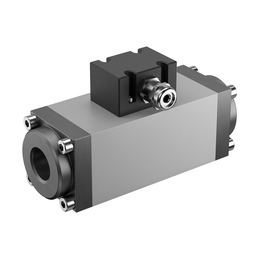
Description Description Function description Fig. 1 Structure of the flowmeter OME series (principle diagram) 1 Connection 4 Ball bearing 2 Connection box/ 5 Measuring housing Smart Solution electronic unit 6 Measuring screw large 3 Measuring screw small Flowmeters belong to the group of rotating displacement meters as screw meters. The liquid current makes the measuring unit rotate. -
Page 16: Linearization
The signals of the sensors are converted into rectangular impulses in the robust connection box. The phase-offset signal and the incremental encoding inputs available in an external KRAL electronic unit can determine the direction of flow and take it into consideration when calculating the total values. The connection box is equipped additionally with a temperature sensor. -
Page 17: Lifting The Flowmeter
Unpacking and checking the state of delivery Unpacking and checking the state of delivery Transportation, storage and disposal 1. On delivery unpack the flowmeter and check for damage during transportation. 2. Report damage during transportation immediately to the manufacturer. 3. Dispose of packing material in accordance with the locally applicable regulations. Lifting the flowmeter WARNING Risk of injury and/or damage to equipment should the flowmeter fall. -
Page 18: Removing The Preservation
Disposal Notice: Store the preserved flowmeter cool and dry and protect it against direct sunlight. Notice: After a longer storage time the manufacturer recommends a recalibration of the flowmeter, see "Recali- bration of the flowmeters", page 26. Removing the preservation Aids: □... -
Page 19: Safety Instructions For Installation And Removal
"Trace heating system", page 9. Installing the flowmeter Flowmeters of the OME series can be operated in any installation position. Notice: Both flow directions are possible. The preferred flow direction is indicated on the rating plate by means of a bright arrow, see Fig. -
Page 20: Preferred Installation Variant
Installing the flowmeter Preferred installation variant Flow vertically from bottom to top ► Preferred installation variant. Recommendations for alternative installation variants Flow vertically from top to bottom No vertical installation with open outlet ► Ensure that the liquid does not flow freely out ►... -
Page 21: Protect The Flowmeter Against Contamination
Installing the flowmeter CAUTION Measuring error through air in the pipe system and/or incorrect installation of the flowmeter. ► In the case of horizontal installation of the flowmeter at the highest point of the pipe system an air pocket can arise that results in measuring errors. ►... -
Page 22: Electrical Connection
Electrical connection 1. Remove the protective covers and store them. 2. Install the flowmeter stress-free in the circular pipeline. Take the preferred flow direction into consi- deration and ensure that the connection of the connection box or Smart Solution electronic unit remains accessible 3. -
Page 23: Removing The Flowmeter
Removing the flowmeter Removing the flowmeter Prerequisite: □ System switched off Aids: □ Vessels for leaking pumped liquid WARNING Risk of injury through hot surface of the flowmeter. ► Wear personal protective equipment and/or let the device cool down to the ambient temperature. WARNING Risk of injury through emitted hot, poisonous or corrosive pumped liquid when removing the flowme- ter. -
Page 24: Commissioning
Commissioning Commissioning Operation Cleaning the pipe system Notice: Soiling in the pipe system impairs the service life of the flowmeter. In order to protect the flowmeter against soiling the manufacturer generally recommends the installation of an operating filter. Notice: Through the calibration, the internal components of the flowmeter are wetted with calibration liquid. If required, use an appropriate solvent to flush the flowmeter. -
Page 25: During Operation
During operation CAUTION Measuring error through gas inclusion in the pipe system. ► Before commissioning, make sure that the flowmeter is filled. ► Deaerate the pipe system. CAUTION Increased wear and/or blocking of the flowmeter due to solid particles or abrasive fine particles in the liquid. -
Page 26: Safety Instructions For Maintenance
Safety instructions for maintenance Safety instructions for maintenance Maintenance The following safety instructions must be observed during all the repair work: ► All the work may only be carried out by authorized qualified personnel. ► Wear protective clothing during all the work. ►... -
Page 27: Mounting Instructions Ome
Mounting instructions OME Mounting instructions OME Removing seals and bearings 915.1* 915.2* 817.1 070.1* 817.3 070.2* 739.1 739.2 Fig. 1 Fig. 2 Fig. 3 817.2 672.1 817.1 817.4 672.2 817.3 Fig. 4 Distance sleeve 739.2 O-ring 070.1* End cover 817.1 Deep-groove ball bearing 070.2* End cover... -
Page 28: Installing Seals And Bearings
Mounting instructions OME Installing seals and bearings 1. Insert the O-ring 739.2 into the measuring housing 128. Place on the end cover 070.2*, tighten the socket screws 915.2* with torque, see Tab. 1, page 37. 2. Press the ball bearings 817.1, 817.2, 817.3 and 817.4 onto the measuring screws. Notice: Press on only over the inner ring! 3. -
Page 29: Mounting Instructions Connection Box
Mounting instructions connection box Mounting instructions connection box Removing the sensor insert 915.3 Fig. 5 Position of the thermally conductive foil 623.5 623.2 623.1 623.4 Measuring housing Flat gasket 623.3 Connection box (cover) Sensor insert 623.1 Screws 623.2 Upper circuit board 623.3 Hex standoffs 623.4... -
Page 30: Connection Box
Mounting instructions connection box Terminal strip Designation Terminal strip Designation Com. t 10 – 30 V Com. t Sig. 1 Q Sig. t Sig. 2 Q Tab. 2 Connection table connection box Checking the function of the connection box 1. Pick up: Simulate a very low flow and measure the signal voltage between terminal strip 1 and 3, as well as between 1 and 4. -
Page 31: Mounting Instructions Smart Solution Electronic Unit
Mounting instructions Smart Solution electronic unit Mounting instructions Smart Solution electronic unit Removing Smart Solution electronic unit 630.7 630.2 630.6 630.4 630.3 Fig. 7 Position of thermal conduc- 630.8 ting foil 630.5 630.1 Measuring housing Flat gasket 623.4* 623.3* Hexagonal spacer 623.4* Lower circuit board 623.3*... -
Page 32: Installing The Smart Solution Electronic Unit
Mounting instructions Smart Solution electronic unit Installing the Smart Solution electronic unit 1. Install the sensor insert, see "Installing the sensor insert", page 29. 2. Place the housing 630.1 onto the flat gasket 222 and screw tight with socket screws 630.5. 3. -
Page 33: Possible Faults
Possible faults Faults can have different causes. The following tables list the symptoms of a fault, the possible causes Troubleshooting and measures for elimination. Possible faults Fault Cause/Remedy □ Flowmeter leaks 1, 2 □ No flow 3, 11, 12, 24, 26, 27 □... - Page 34 Troubleshooting Cause Remedy Flow rate fluctuations too high ► Ensure a continuous flow rate by taking suitable measures (use of a different pump, valve, damper, etc.). - or - ► Smoothen the indication, while observing the electronic operating instructions. Filling amount too low ►...
-
Page 35: Spare Parts
Spare parts Spare parts Appendix Maintenance kit OME 13 – 52 Notice: The maintenance kit contains only the numbered parts and is only supplied completely. 739.2 739.1 817.4 817.3 817.2 817.1 Fig. 1 Maintenance kit OME 13 – 52 Qty. Pos. -
Page 36: Sensor Insert For Connection Box
Spare parts Sensor insert for connection box Notice: The kits contain only the numbered parts and are only supplied completely. Fig. 2 Sensor insert (incl. thermally conductive foil) Qty. Pos. no. Part Sensor insert Smart Solution electronic unit Notice: The kits contain only the numbered parts and are only supplied completely. Fig. -
Page 37: Tightening Torques
Tightening torques Tightening torques Tightening torque [Nm] for screws with metric threads + head cont- With thread measured in act surfaces inches Stainless steel Countersunk Screw plugs with screws A2 and A4 screws elastomer seal 8.8 + 10.9 Alu* – G 1/8"... -
Page 38: Notes
Notes Notes OIO 20en Edition 2020-05 Operating Instructions... - Page 39 Notes Operating Instructions OIO 20en Edition 2020-05...
- Page 40 KRAL GmbH, 6890 Lustenau, Austria, Tel.: +43 / 55 77 / 8 66 44 - 0, E-Mail: kral@kral.at www.kral.at...
Need help?
Do you have a question about the OME Series and is the answer not in the manual?
Questions and answers