Table of Contents
Advertisement
Quick Links
Introduction
The
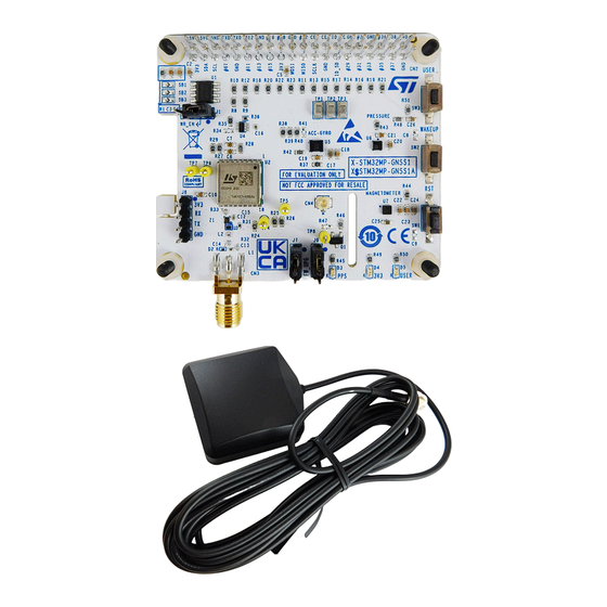
X-STM32MP-GNSS1
expansion board for the global navigation satellite system (GNSS) receiver which embeds the
following devices:
•
The
Teseo-LIV3FL
module for Low power GNSS positioning along with sensor for position accuracy.
•
The
ISM330DHCX
iNEMO 3-axis accelerometer and 3-axis gyroscope
•
The
IIS2MDC
3-axis magnetometer
•
The
ILPS22QS
pressure sensor
•
The external LNA and SAW filter
•
The external antenna amplifies any weak signals to improve the quality of data received.
•
Switches & LEDs present
The
X-STM32MP-GNSS1
interfaces with the STM32MP157F-DK2 board via a 40-pin GPIO connector, using I²C, SPI, and
GPIO interfaces.
The
X-STM32MP-GNSS1
expansion board is compatible with both the STM32MP157F-DK2 and Raspberry Pi GPIO expansion
connector layout.
UM3237 - Rev 1 - October 2023
For further information contact your local STMicroelectronics sales office.
Getting started with X-STM32MP-GNSS1 expansion board
Figure 1.
X-STM32MP-GNSS1 expansion board
UM3237
User manual
www.st.com
Advertisement
Table of Contents

Related Manuals for ST X-STM32MP-GNSS1


Summary of Contents for ST X-STM32MP-GNSS1
-
Page 1: Figure 1. X-Stm32Mp-Gnss1 Expansion Board
UM3237 User manual Getting started with X-STM32MP-GNSS1 expansion board Introduction X-STM32MP-GNSS1 expansion board for the global navigation satellite system (GNSS) receiver which embeds the following devices: • Teseo-LIV3FL module for Low power GNSS positioning along with sensor for position accuracy. -
Page 2: Overview
Overview X-STM32MP-GNSS1 is powered via a standard 3.3 V supply through the STM32MP157F-DK2 GPIO connector. The figure below shows the component placement on the board. Figure 2. X-STM32MP-GNSS1 component placement details 40 PIN GPIO CONNECTOR M24C32-RMN6TP USER SWITCH ILPS22QS TPS22943... -
Page 3: System Requirements
UM3237 System requirements Figure 3. System block diagram System requirements To use the X-STM32MP-GNSS1, you need: • X-STM32MP-GNSS1 expansion board • STM32MP157F-DK2 discovery kit • A laptop/desktop (with Windows 10 or above) • A USB Type-A to micro-B USB cable (for connection as a virtual serial device, if required) •... -
Page 4: Board Setup
Note: Boards can damage if not connected properly. Figure 4. X-STM32MP-GNSS1 connected to STM32MP157F-DK2 Step 4. Power the STM32MP157F-DK2 using the USB Type-C® cable. Step 5. Program the supported firmware in the microSD™ card of the STM32MP157F-DK2 board. The X- STM32MP-GNSS1 board is ready for use. -
Page 5: Component Description
UM3237 Component description Component description The board comprises the following key devices: EEPROM Section M24C32 is a 32-Kbit I2C-compatible EEPROM (electrically erasable programmable memory) organized as 4 K × 8 bits. Table 1. M24C32-R package details Features Description Order code M24C32-RMN6TP Package Operating voltage... -
Page 6: Teseo-Liv3Fl Module Section
UM3237 Teseo-LIV3FL module section Teseo-LIV3FL module section Teseo-LIV3FL module is based on the TESEO III single-die standalone positioning receiver IC, which is a low-power tiny GNSS receiver. Within its 9.7 x 10.1 mm tiny size, the Teseo-LIV3FL offers superior accuracy as it has integrated temperature, compensated crystal oscillator (TCXO), and a reduced time to first fix (TTFF) due to its dedicated real-time clock (RTC) oscillator. -
Page 7: Lna (Low Noise Amplifier)
UM3237 LNA (low noise amplifier) LNA (low noise amplifier) An external low noise amplifier (LNA) is also present to amplify the weak signals received. The low noise amplifier (BGA824N6) ranges from 1550 MHz to 1615 MHz. It provides a 17.0 dB gain and 0.55 dB noise figure at a current consumption of 3.8 mA. -
Page 8: Pressure Sensor Ilps22Qs
UM3237 Pressure Sensor ILPS22QS An unmatched set of embedded features (machine learning core, programmable FSM, FIFO, sensor hub, event decoding and interrupts) are enablers for implementing smart and complex sensor nodes which deliver high performance at very low power. The ISM330DHCX is available in a 14-lead plastic land grid array (LGA) package. Table 5. -
Page 9: Magnetometer Sensor Iis2Mdc
UM3237 Magnetometer sensor IIS2MDC Figure 9. ILPS22QSTR Circuit ILP S 22QS _3V3 ILP S 22QS _3V3 I2C_S CL S CL/S P C I2C_S DA VDD_IO S DA/S DI/S DO AH2/QVAR2 GND_IO 100nF 100nF ILP S 22QS _3V3 AH1/QVAR1 ILP S 22QS Pressure Sensor Magnetometer sensor IIS2MDC The IIS2MDC is a high-accuracy, ultra-low-power 3-axis digital magnetic sensor. -
Page 10: Leds And Switches
UM3237 LEDs and Switches LEDs and Switches 3 LEDs are used as an output to indicate to the user of the functioning of the module. Red LED glows constantly indicating adequate power supply is available to the board. Green LED blinks continuously to indicate the functioning of PPS (pulse per second). -
Page 11: 40 Pin Gpio Connector
UM3237 40 PIN GPIO connector 40 PIN GPIO connector The on-board devices will be controlled through the main board using various peripheral pins available on the GPIO connector. The series resistors are used to isolate the pins of GPIO connector. Figure 12. -
Page 12: Table 8. Gpio Connector Pin Configuration
UM3237 40 PIN GPIO connector Table 8. GPIO connector pin configuration Pin No Name STM32MP157F-DK2 Pin No Name STM32MP157F-DK2 I2C_SDA PA12 / I2C5_SDA I2C_SCL PA11 / I2C5_SCL PA8/ MCO1 TESEO-LIV3FL_UART_RX PB10 / USART3_TX TESEO-LIV3FL_UART_TX PB12 / USART3_RX TESEO-LIV3FL_WAKEUP PG8 / USART3_RTS PI5 / SAI2_SCKA TESEO-LIV3FL_RESET PD7 / SDMMC3_D3... -
Page 13: Schematic Diagrams
Schematic diagrams Figure 13. X-STM32MP-GNSS1 schematic diagram (1 of 9) P a ge 3_Conne ctor GP IO_Expa ns ion_Conne ctor LED_US ER LED_US ER EEP ROM_ID_S D EEP ROM_ID_S D S WITCH_US ER S WITCH_US ER EEP ROM_ID_S C EEP ROM_ID_S C... -
Page 14: Figure 14. X-Stm32Mp-Gnss1 Schematic Diagram (2 Of 9)
Figure 14. X-STM32MP-GNSS1 schematic diagram (2 of 9) S B1 S B2 S B3 Ope n Ope n Ope n 100nF 3.9K 3.9K EEP ROM_ID_S C S CL EEP ROM_ID_S D VS S S DA M24C32-RMN6TP 3-pin Ma le He a de r... -
Page 15: Figure 15. X-Stm32Mp-Gnss1 Schematic Diagram (3 Of 9)
Figure 15. X-STM32MP-GNSS1 schematic diagram (3 of 9) 100nF 100nF 100nF S DA S CL TP 1 TP 2 100nF TP 3 ID_S D ID_S C He a de r 20X2_fe ma le 1.5k 1.5k S DA I2C_S DA TES EO-LIV3FL_RES ET... -
Page 16: Figure 16. X-Stm32Mp-Gnss1 Schematic Diagram (4 Of 9)
Figure 16. X-STM32MP-GNSS1 schematic diagram (4 of 9) TES EO-LIV3FL_UART_TX J R1 CON_TX S HUNT 2.54 mm. HEADER1X3 TP 4 RF_IN UART-TX RF_IN TES EO-LIV3FL_UART_RX J R2 ANTOFF UART-RX AntOFF S HUNT 2.54 mm. CON_RX HEADER1X3 TP 5 VCC_RF RES 2... -
Page 17: Figure 17. X-Stm32Mp-Gnss1 Schematic Diagram (5 Of 9)
Figure 17. X-STM32MP-GNSS1 schematic diagram (5 of 9) VCC_RF VANT ANTOFF 120pF L_0402 100nH 120pF 120pF RF_IN S MA_HRZ B39162B4327P 810 BGA824N6 ES DARF02-1BU2CK VCC_RF TP S 22943 VANT VOUT ANTOFF 100K VCC_RF Figure 18. X-STM32MP-GNSS1 schematic diagram (6 of 9) -
Page 18: Figure 19. X-Stm32Mp-Gnss1 Schematic Diagram (7 Of 9)
Figure 19. X-STM32MP-GNSS1 schematic diagram (7 of 9) ILP S 22QS _3V3 ILP S 22QS _3V3 I2C_S CL S CL/S P C I2C_S DA VDD_IO S DA/S DI/S DO AH2/QVAR2 GND_IO ILP S 22QS _3V3 100nF 100nF AH1/QVAR1 ILP S 22QS Pressure Sensor Figure 20. -
Page 19: Figure 21. X-Stm32Mp-Gnss1 Schematic Diagram (9 Of 9)
Figure 21. X-STM32MP-GNSS1 schematic diagram (9 of 9) LED GREEN TP 8 TES EO-LIV3FL_P P S 2S TR1160 U.FL-R-S MT-1(10) LED_US ER 4.7K S WITCH_US ER S W3 100nF S P S T S W LED RED LED YELLOW... -
Page 20: Bill Of Materials
UM3237 Bill of materials Bill of materials Table 9. X-STM32MP-GNSS1 bill of materials Item Q.ty Ref. Part/value Description Manufacturer Order code Battery Holder (Open) Coin, S8421-45R Harwin Inc. S8421-45R 20.0mm 1 Cell SMD (SMT) Tab C1 C2 C3 C4 C5 C6 C7 C10 C18 CAP CER 0.1UF... - Page 21 UM3237 Bill of materials Item Q.ty Ref. Part/value Description Manufacturer Order code CONN HEADER J6 J7 HEADER1X3 Samtec Inc. TSW-103-07-F-S .100 STR 3POS CONN HEADER con4-strip-male Samtec Inc. TSW-104-07-F-S .100 STR 4POS Shunt Samtec 2pins pitch JR1 JR2 SHUNT 2.54 mm. 1-382811-6 2.54mm - Black Connectivity /AMP...
- Page 22 UM3237 Bill of materials Item Q.ty Ref. Part/value Description Manufacturer Order code RES SMD 1K OHM 1% 1/10W Vishay Dale CRCW06031K00FKEA 0603 RES 75 OHM 1% Yageo RC0603FR-0775RL 1/10W 0603 RES SMD 22K OHM 5% 1/10W Vishay Dale CRCW060322K0JNEA 0603 RES 300 OHM Stackpole R49 R50...
-
Page 23: Table 10. Misc
UM3237 Bill of materials Table 10. Misc Item Q.ty Ref. Part/value Description Manufacturer Order code M3x0.5 Hex Nut 0.217" (5.50mm) Nylon Würth Elektronik 709940300 Spacer Hex Standoff Threaded M3x0.5 Nylon 0.472" (12.00mm) Natural Essentra 36M30MF012 Antenna Antenna 27dB Gain 1615MHz INPAQ B3G02G-S3-XX-A UM3237 - Rev 1... -
Page 24: Stm32Mp-Gnss1 Versions
X-STM32MP-GNSS1 versions PCB version Schematic diagrams Bill of materials X$STM32MP-GNSS1A X$STM32MP-GNSS1A schematic diagrams X$STM32MP-GNSS1A bill of materials 1. This code identifies the X-STM32MP-GNSS1 evaluation board first version. It is printed on the board PCB. UM3237 - Rev 1 page 24/30... -
Page 25: Regulatory Compliance Information
UM3237 Regulatory compliance information Regulatory compliance information Notice for US Federal Communication Commission (FCC) This kit is designed to allow: (1) Product developers to evaluate electronic components, circuitry, or software associated with the kit to determine whether to incorporate such items in a finished product and (2) Software developers to write software applications for use with the end product. -
Page 26: Revision History
UM3237 Revision history Table 12. Document revision history Date Revision Changes 31-Oct-2023 Initial release. UM3237 - Rev 1 page 26/30... -
Page 27: Table Of Contents
X-STM32MP-GNSS1 versions ........ -
Page 28: List Of Tables
X-STM32MP-GNSS1 bill of materials ........ -
Page 29: List Of Figures
X-STM32MP-GNSS1 connected to STM32MP157F-DK2 ........ - Page 30 ST’s terms and conditions of sale in place at the time of order acknowledgment. Purchasers are solely responsible for the choice, selection, and use of ST products and ST assumes no liability for application assistance or the design of purchasers’...
Need help?
Do you have a question about the X-STM32MP-GNSS1 and is the answer not in the manual?
Questions and answers