Table of Contents
Advertisement
Quick Links
UM1820
User manual
MEMS inertial and environmental sensor expansion board for
STM32 Nucleo
Introduction
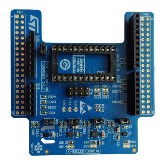
The X-NUCLEO-IKS01A1 is a MEMS inertial and environmental sensor evaluation board
which can be used to expand the STM32 Nucleo system. It is also compatible with the
Arduino UNO R3 connector layout and is designed around the STMicroelectronics 3-axis
accelerometer plus 3-axis gyroscope (LSM6DS0), 3-axis magnetometer (LIS3MDL),
humidity (HTS221) and pressure (LPS25H) sensors. The X-NUCLEO-IKS01A1 interfaces
2
2
with the STM32 MCU via the I
C pin, and the user can change the default I
C port.
This document details the hardware requirements and board connections for the X-
NUCLEO-IKS01A1 MEMS and environmental sensor expansion board for STM32 Nucleo.
Figure 1. X-NUCLEO-IKS01A1 evaluation board
November 2014
DocID026959 Rev 1
1/14
www.st.com
14
Advertisement
Table of Contents

Related Manuals for ST X-NUCLEO-IKS01A1


Summary of Contents for ST X-NUCLEO-IKS01A1
- Page 1 STM32 Nucleo Introduction The X-NUCLEO-IKS01A1 is a MEMS inertial and environmental sensor evaluation board which can be used to expand the STM32 Nucleo system. It is also compatible with the Arduino UNO R3 connector layout and is designed around the STMicroelectronics 3-axis accelerometer plus 3-axis gyroscope (LSM6DS0), 3-axis magnetometer (LIS3MDL), humidity (HTS221) and pressure (LPS25H) sensors.
-
Page 2: Table Of Contents
Contents UM1820 Contents Getting started ..........3 Hardware requirements . -
Page 3: Getting Started
Hardware requirements The X-NUCLEO-IKS01A1 is an expansion board for use with STM32 Nucleo boards (please refer to UM1724 on www.st.com for further information). To function correctly, the STM32 Nucleo board must be connected to the X-NUCLEO-IKS01A1 board, as shown in Figure Figure 2. -
Page 4: System Requirements
System requirements UM1820 System requirements Using the Nucleo boards with the X-NUCLEO-IKS01A1 expansion board requires the following software and hardware: ® • a Windows (XP, Vista, 7, 8) PC on which to install the software • a USB type A to Mini-B USB cable to connect the Nucleo to the PC for installation of the board firmware package (order code: X-CUBE-IKS01A1). -
Page 5: Hardware Description
LPS25H: MEMS pressure sensor, 260-1260 hPa absolute digital output barometer – HTS221: Capacitive digital relative humidity and temperature sensor The X-NUCLEO-IKS01A1 also has a DIL24 socket to connect and test additional sensors (i.e. UVI sensors, other MEMS sensor, etc…). The sensors are connected on a single bus via I C and each device has a separate power supply to allow measurement of the power consumption of each single sensor. -
Page 6: Sensor Current Consumption Measurement
DIP24 socket for adapter boards Sensors can be added via adapter boards connected to the DIL24 socket J1. Please visit www.st.com to find other sensors that are available. As there are various interrupt signal assignments to DIL24 pins, the appropriate pin can be selected using the JP6 header. -
Page 7: Connectors
UM1820 Hardware description Connectors The pin assignments for the Arduino UNO R3 and the Morpho connectors are shown in Table 4 Table 5 respectively. Table 4. Arduino UNO R3 connector table Connector Signal Remarks C SDA C SCL 3.3V 3.3V INT1 (DIL24) INT2 (DIL24) LIS3MDL INT1... - Page 8 Hardware description UM1820 Table 5. ST Morpho connector table Connector Signal Remarks 3.3V 3.3V INT1 (DIL24) INT2 (DIL24) LIS3MDL INT1 LIS3MDL DRDY C SCL C SDA HTS221 DRDY CN10 LPS25H INT1 LSM6DS0 INT1 USER INT (optional) 1. Any unlisted pins are not connected.
-
Page 9: Board Schematic And Bill Of Material
UM1820 Board schematic and bill of material Board schematic and bill of material This section contains the bill of material, schematic and layout of the X-NUCLEO-IKS01A1. Bill of material Table 6. X-NUCLEO-IKS01 bill of material Package Quantity Designator Value Part number... - Page 10 SB14, SB15, Solder Bridge Open 0603 SB17 Header 1x1 pins, TP1, TP2, TP3 Header 1x1 Not mounted 2.54mm, straight LIS3MDL LIS3MDL ST-SUPPLY LGA 2x2 12L LSM3DS0 LSM6DS0 ST-SUPPLY LGA 3x3 16L HTS221 HTS221 ST-SUPPLY HLGA 2x2 6L HCLGA 2.5x2.5 LPS25H...
-
Page 11: Schematic
UM1820 Board schematic and bill of material Schematic Figure 4. X-NUCLEO-IKS01A1 circuit schematic I2C_SCL I2C_SDA GSPG29092014DI1150 DocID026959 Rev 1 11/14... -
Page 12: Layout
Layout UM1820 Layout Figure 5. X-NUCLEO-IKS01A1 top side layout Figure 6. X-NUCLEO-IKS01A1 bottom side layout 12/14 DocID026959 Rev 1... -
Page 13: Revision History
UM1820 Revision history Revision history Table 7. Document revision history Date Revision Changes 06-Nov-2014 Initial release. DocID026959 Rev 1 13/14... - Page 14 ST products and/or to this document at any time without notice. Purchasers should obtain the latest relevant information on ST products before placing orders. ST products are sold pursuant to ST’s terms and conditions of sale in place at the time of order acknowledgement.
Need help?
Do you have a question about the X-NUCLEO-IKS01A1 and is the answer not in the manual?
Questions and answers