Table of Contents
Advertisement
Quick Links
UM1900
User manual
Getting started with the digital MEMS microphone expansion
board based on MP34DT01-M for STM32 Nucleo
Introduction
The X-NUCLEO-CCA02M1 is an evaluation board based on digital MEMS microphones. It is compatible
with the Morpho connector layout and is designed around STMicroelectronics MP34DT01-M digital
microphones. It has two microphones soldered on board and it is compatible with digital microphone
coupon boards such as STEVAL-MKI129Vx and STEVAL-MKI155Vx. The X-NUCLEO-CCA02M1
allows synchronized acquisition and streaming of up to four microphones through peripherals I²S, SPI or
DFSDM. It represents a quick and easy solution for the development of microphone-based applications,
as well as a starting point for audio algorithm implementation.
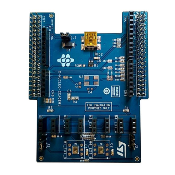
Figure 1: X-NUCLEO-CCA02M1 evaluation board
May 2017
DocID027905 Rev 4
1/20
www.st.com
Advertisement
Table of Contents

Related Manuals for ST X-NUCLEO-CCA02M1


Summary of Contents for ST X-NUCLEO-CCA02M1
-
Page 1: Figure 1: X-Nucleo-Cca02M1 Evaluation Board
MP34DT01-M for STM32 Nucleo Introduction The X-NUCLEO-CCA02M1 is an evaluation board based on digital MEMS microphones. It is compatible with the Morpho connector layout and is designed around STMicroelectronics MP34DT01-M digital microphones. It has two microphones soldered on board and it is compatible with digital microphone coupon boards such as STEVAL-MKI129Vx and STEVAL-MKI155Vx. -
Page 2: Table Of Contents
Contents UM1900 Contents Getting started ................. 5 Hardware requirements ..............5 System requirements ................ 5 Hardware description ..............7 USB connector and power source ............. 7 Audio acquisition strategy ..............8 2.2.1 DFSDM microphone acquisition ............8 2.2.2 I²S and SPI microphone acquisition ........... 8 Solder bridge configurations.............. - Page 3 Table 5: Solder bridge configuration for 2 microphone acquisition ............12 Table 6: Solder bridge configuration for 4 microphone acquisition ............13 Table 7: ST morpho connector table ......................15 Table 8: Arduino connector table ......................15 Table 9: Document revision history ......................19...
- Page 4 UM1900 List of figures Figure 1: X-NUCLEO-CCA02M1 evaluation board ..................1 Figure 2: X-NUCLEO-CCA02M1 on STM32 Nucleo board ................ 5 Figure 3: Connection with STEVAL-MKI155V1 ..................7 Figure 4: General acquisition strategy using I²S and SPI ................9 Figure 5: Board schematic (Part 1) ......................16 Figure 6: Board schematic (Part 2) ......................
-
Page 5: Getting Started
This section describes the hardware requirements for the X-NUCLEO-CCA02M1 evaluation board. Hardware requirements The X-NUCLEO-CCA02M1 is an expansion board for use with STM32 Nucleo boards (refer to UM1724 on www.st.com for further information). The STM32 Nucleo board must be connected to the X-NUCLEO-CCA02M1 board, as shown below. - Page 6 PC will complete the demo. The user PC must have the following characteristics: at least 128 MB of RAM 40 MB of available hard disk space for the X-CUBE-MEMSMIC1 firmware package and relative documentation, available on www.st.com. 6/20 DocID027905 Rev 4...
-
Page 7: Hardware Description
6 headers (4 mounted with 2 additional footprints) are available for connecting additional microphones using digital microphone coupon boards (STEVAL- MKI129Vx or STEVAL-MKI155Vx), for further information refer to www.st.com. The connection between the X-NUCLEO-CCA02M1 and the STEVAL-MKI155V1 is shown Figure 3: "Connection with STEVAL-MKI155V1". -
Page 8: Audio Acquisition Strategy
A software demuxing step separates the signal from the two microphones and allows further processing like PDM-to-PCM conversion. For further information regarding MEMS microphone and PDM-to-PCM decimation, please refer to application note AN3998 on www.st.com. 8/20 DocID027905 Rev 4... -
Page 9: Solder Bridge Configurations
Solder bridge configurations Various board configurations are possible, depending on the use cases. MEMS microphones can be plugged into ST morpho pins, and thus to MCU peripherals, with appropriate solder bridges. Clock routing can also be changed according to specific needs. -
Page 10: Sample Use Cases
Hardware description UM1900 Function Solder Bridge Clock from the DFSDM peripheral SB12 I2S clock from MCU SB13 Connects I²S clock directly to MIC clock without passing through timer SB14 Connect I²S clock to MCU timer input channel SB15 Connects MIC12 PDM to MCU DFSDM SB16 Connects MIC34 PDM to MCU DFSDM SB17... -
Page 11: Table 3: Solder Bridge Configuration For 4 Microphone Acquisition
UM1900 Hardware description In addition, J2 must be placed in position 1-2 for on-board microphone acquisition or 2-3 when using an external microphone while J3 must be left open. When acquiring on-board microphones, close SB9 to acquire both of them. 4 microphone acquisition In this case, the PDM line of the third and fourth microphone is also routed to the MCU. -
Page 12: Table 5: Solder Bridge Configuration For 2 Microphone Acquisition
Hardware description UM1900 Status SB15 Open SB16 Open SB17 Open SB18 Open SB19 Open SB20 Open SB21 Open In addition, J2 must be placed in position 1-2 for on-board microphone acquisition or 2-3 when using an external microphone, while J3 must be left open. If using external microphones, do not plug anything in M2_EXT header. -
Page 13: Table 6: Solder Bridge Configuration For 4 Microphone Acquisition
UM1900 Hardware description 4 external microphone acquisition In this case, the I²S peripheral is used to generate a clock frequency that is twice the frequency needed by the microphones, and SPI is configured in slave mode in order to use such timing. -
Page 14: Nucleo 144 Support
Nucleo 144 support UM1900 Nucleo 144 support In order to accept Nucleo-144 boards, morpho header connectors must be soldered on the relevant footprint available on the Nucleo. You only need a pair of 2 x 38 pin stripline connectors for the expansion board; you don't need to solder the whole 2 x 80 pin header. -
Page 15: Connectors
UM1900 Connectors Connectors The pin assignments for the Arduino UNO R3 and the ST morpho connectors are shown in Table 7: "ST morpho connector table" Table 8: "Arduino connector table" respectively. Table 7: ST morpho connector table Connector Signal Remarks... -
Page 16: Board Schematics
Board schematics UM1900 Board schematics Figure 5: Board schematic (Part 1) Figure 6: Board schematic (Part 2) 16/20 DocID027905 Rev 4... -
Page 17: Figure 7: Board Schematic (Part 3)
UM1900 Board schematics Figure 7: Board schematic (Part 3) Figure 8: Board schematic (Part 4) DocID027905 Rev 4 17/20... -
Page 18: Layout
Layout UM1900 Layout Figure 9: Top layout Figure 10: Bottom layout 18/20 DocID027905 Rev 4... -
Page 19: Revision History
UM1900 Revision history Revision history Table 9: Document revision history Date Revision Changes 28-May-2015 Initial release. Minor text edits throughout document. Updated Section "Introduction". 28-Jan-2016 Updated Section 3.3: "Audio acquisition strategy". Updated Section 3.4: "Solder bridge configurations". 14-Jul-2016 Added Section 4: "Nucleo 144 support". Updated Section 2.3.2.2: "Jumper settings for I²S-plus-SPI-based 09-May-2017... - Page 20 ST products and/or to this document at any time without notice. Purchasers should obtain the latest relevant information on ST products before placing orders. ST products are sold pursuant to ST’s terms and conditions of sale in place at the time of order acknowledgement.
Need help?
Do you have a question about the X-NUCLEO-CCA02M1 and is the answer not in the manual?
Questions and answers