Table of Contents
Advertisement
Quick Links
UM2708
User manual
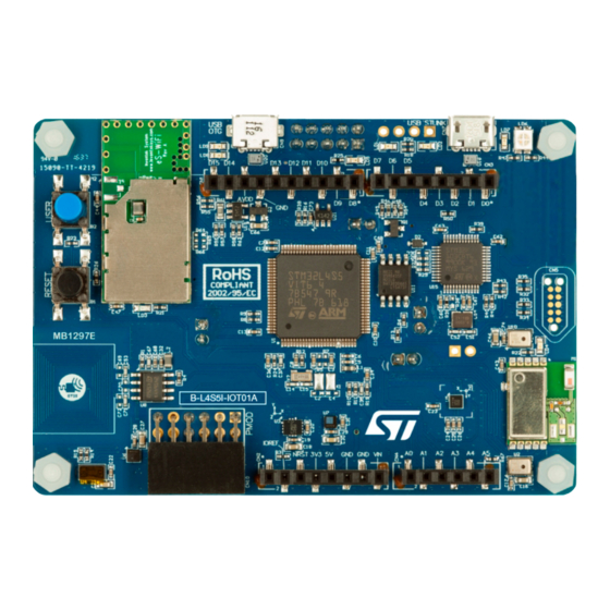
Discovery kit for IoT node, multi-channel communication with STM32L4+ Series
Introduction
The
B-L4S5I-IOT01A
Discovery kit for the IoT node allows the user to develop applications with a direct connection to the cloud
servers.
The B-L4S5I-IOT01A Discovery kit for the IoT node enables a wide diversity of applications by exploiting low-power multilink
®
®
communication (Bluetooth
Low Energy, Wi‑Fi
, NFC), multiway sensing (detection, environmental awareness) and
®
®
Arm
Cortex
-M4 core-based STM32L4+ Series features.
®
™
ARDUINO
Uno V3 and Pmod
connectivity provide unlimited expansion capabilities with a large choice of specialized add-on
boards.
The B-L4S5I-IOT01A Discovery kit for the IoT node includes an ST-LINK debugger/programmer and comes with the
comprehensive STM32CubeL4 MCU Package, which provides an STM32 comprehensive software HAL library as well as
various software examples to seamlessly connect to cloud servers.
Figure 1.
B-L4S5I-IOT01A Discovery kit for the IoT node
Picture is not contractual.
UM2708 - Rev 1 - April 2020
www.st.com
For further information contact your local STMicroelectronics sales office.
Advertisement
Table of Contents

Related Manuals for ST B-L4S5I-IOT01A


Summary of Contents for ST B-L4S5I-IOT01A
- Page 1 Discovery kit for the IoT node allows the user to develop applications with a direct connection to the cloud servers. The B-L4S5I-IOT01A Discovery kit for the IoT node enables a wide diversity of applications by exploiting low-power multilink ® ®...
-
Page 2: Features
• Flexible power-supply options: ST-LINK, USB V or external sources • On-board ST-LINK/V2-1 debugger/programmer with USB re-enumeration capability: mass storage, Virtual COM port, and debug port • Comprehensive free software libraries and examples available with the STM32Cube MCU Package ™... -
Page 3: Ordering Information
Evaluation tools marked as “ES” or “E” are not yet qualified and therefore not ready to be used as reference design or in production. Any consequences deriving from such usage will not be at ST charge. In no event, ST will be liable for any customer usage of these engineering sample tools as reference designs or in production. -
Page 4: Development Environment
UM2708 Development environment Development environment The B-L4S5I-IOT01A Discovery kit for the IoT node runs with the STM32L4S5VI 32-bit microcontroller based on ® ® the Arm Cortex -M4 core. System requirements ® ® ® • Windows OS (7, 8 and 10), Linux 64-bit, or macOS •... -
Page 5: Conventions
UM2708 Conventions Conventions Table 3 provides the conventions used for the ON and OFF settings in the present document. Table 3. ON/OFF convention Convention Definition Jumper JPx ON Jumper fitted Jumper JPx OFF Jumper not fitted Jumper JPx [1-2] Jumper fitted between Pin 1 and Pin 2 Solder bridge SBx ON SBx connections closed by 0 Ω... -
Page 6: Delivery Recommendations
UM2708 Delivery recommendations Delivery recommendations Before the first use, make sure that no damage occurred to the board during shipment and no socketed components are not firmly fixed in their sockets or loose in the plastic bag. UM2708 - Rev 1 page 6/43... -
Page 7: Hardware Layout And Configuration
UM2708 Hardware layout and configuration Hardware layout and configuration The B-L4S5I-IOT01A Discovery kit for the IoT node is designed around the STM32L4S5VIT6U target microcontroller in a 100-pin LQFP package. The hardware block diagram (Refer to Figure 2) illustrates the ®... -
Page 8: Figure 3. B-L4S5I-Iot01A Discovery Kit For The Iot Node Layout (Top View)
Figure 3. B-L4S5I-IOT01A Discovery kit for the IoT node layout (top view) -
Page 9: Figure 4. B-L4S5I-Iot01A Discovery Kit For The Iot Node Layout (Bottom View)
Figure 4. B-L4S5I-IOT01A Discovery kit for the IoT node layout (bottom view) -
Page 10: Figure 5. B-L4S5I-Iot01A Discovery Kit For The Iot Node Mechanical Drawing In Millimeters
Figure 5. B-L4S5I-IOT01A Discovery kit for the IoT node mechanical drawing in millimeters... -
Page 11: Embedded Stlink/V2-1
In case the B-L4S5I-IOT01A Discovery kit for the IoT node is connected to the PC before the driver is installed, some Discovery board interfaces may be declared as “Unknown” in the PC device manager. In this case, the user... -
Page 12: Power Supply
Power supply The B-L4S5I-IOT01A Discovery kit for the IoT node is designed to be powered by a 5 V DC power supply. It is possible to configure the B-L4S5I-IOT01A Discovery kit for the IoT node to use any of the following five sources for the power supply: 5V_ST_LINK, 5V_ARD, 5V_USB_FS, 5V_VBAT, and 5V_USB_CHARGER. -
Page 13: Figure 8. Jp4: 5V_Ard Selection From Cn6 (Vin)
UM2708 Power supply Figure 8. JP4: 5V_ARD selection from CN6 (VIN) 5V_ST_LINK 5V_ARD 5V_USB_FS 5V_VBAT 5V_USB_CHARGER 5V_USB_FS (Refer to Figure This is the DC power with 500 mA limitation from CN9, the USB OTG FS Micro-AB connector. In this case, the JP4 jumper must be fitted between pin 5 and pin 6 to select the 5V_USB_FS power source on the JP4 silkscreen. -
Page 14: Figure 10. Jp4: 5V_Vbat
In this specific case only, the resistor R30 must be soldered, to allow the board to be powered anyway. Caution: Do not connect the PC to the ST-LINK (CN7) when R30 is soldered. The PC may be damaged or the board may not be powered correctly. UM2708 - Rev 1... -
Page 15: Figure 12. Power Tree
UM2708 Power supply The green LED LD5 is lit when the B-L4S5I-IOT01A Discovery kit for the IoT node is powered by the 5 V correctly. The power tree is shown in Figure 12. Power tree. Figure 12. Power tree 5V_USB_ST_Link... -
Page 16: Programming And Debugging When The Power Supply Is Not From St-Link (5V_St_Link)
0-ohm resistor (0402 size) at the R7 position The B-L4S5I-IOT01A Discovery kit for the IoT node can be powered by the USB connectors at 5 V DC with 500 mA current limitation. A USB power switch (IC19) is also connected to V and provides power to CN9. -
Page 17: Quad-Spi Nor Flash Memory
6.9.1 ® Bluetooth (V4.1 compliant) SPBTLE-RF module The ST SPBTLE-RF module (M1) is implemented on the top side of the B-L4S5I-IOT01A Discovery kit for the IoT node. ® The SPBTLE-RF is an easy to use Bluetooth smart master-slave network processor module, compliant with ®... -
Page 18: Inventek Systems Ism43362-M3G-L44 (802.11 B/G/N Compliant Wi-Fi ® Module)
Inventek Systems ISM43362-M3G-L44 (802.11 b/g/n compliant Wi‑Fi module) The Inventek Systems ISM43362-M3G-L44 module (M2) is implemented on the top side of the B-L4S5I-IOT01A Discovery kit for the IoT node This module is an embedded (eS-WiFi) wireless Internet Connectivity device. The ®... -
Page 19: Dynamic Nfc Tag Based On St25Dv04K With Its Printed Nfc Antenna
UM2708 RF modules The main features of the Inventek system ISM43362-M3G-L44 module are: • Based on the Broadcom BCM43362 MAC/Baseband/Radio device • Supports Broadcom WICED SDK ® ® • CPU Arm Cortex -M3 32-bit RISC core from STMicroelectronics • IEEE 802.11n D7.0, OFDM-72.2 Mbps, single-stream width of 20 MHz, and short GI •... -
Page 20: Stmicroelectronics Sensors
SPSGRF-915). The footprint is implemented (M3 designation), but no module is soldered. 6.10 STMicroelectronics sensors Several STMicroelectronics sensors are available on the B-L4S5I-IOT01A Discovery kit for the IoT node and are listed below: • Two on-board ST-MEMS audio sensor omnidirectional digital microphones (MP34DT01) •... -
Page 21: Capacitive Digital Sensor For Relative Humidity And Temperature (Hts221)
UM2708 STMicroelectronics sensors On the B-L4S5I-IOT01A Discovery kit for the IoT node, there are two MP34DT01 microphones: one with LR pulled to VDD and the second with LR pulled low. DFSDM1_CKOUT and DFSDM1_DATIN2 are connected to both. In addition, both microphones are spaced at 21 mm apart for the beamforming algorithm to work. Indeed, several algorithm configurations are available for the user to find the best trade-off between audio output quality and resource consumption. -
Page 22: 260 Hpa To 1260 Hpa Absolute Digital Output Barometer (Lps22Hb)
The device comprises a sensing element and an IC interface which communicates from the sensing element to the application through I2C or SPI. On the B-L4S5I-IOT01A Discovery kit for the IoT node, the I2C2 bus from STM32L4S5VIT6U is used. -
Page 23: Stsafe-A110
UM2708 STSAFE-A110 The main features of VL53L0X are listed below. • Fully integrated miniature module: – 940 nm Laser VCSEL – VCSEL driver – Ranging sensor with an advanced embedded microcontroller – 4.4 mm x 2.4 mm x 1.0 mm size •... -
Page 24: Buttons And Leds
Buttons and LEDs The black button (B1) located on the middle left side is the reset of the STM32L4S5VIT6Umicrocontroller. Refer to Figure 3. B-L4S5I-IOT01A Discovery kit for the IoT node layout (top view). The blue button (B2) located on the top left side is available to be used as a digital input or as an alternate wake- up function. -
Page 25: I 2 C Addresses Of Modules Used On Mb1297
Blue LED4 (BLE) PC9, Bluetooth activity Green 5V Power 5 V available Bicolor (Red and green) ST-LINK COM Green during communication Fault Power Current higher than 750 mA OCRCR Green 5 V USB available 6.13 C addresses of modules used on MB1297... -
Page 26: Connectors
UM2708 Connectors Connectors Nine connectors are implemented on the B-L4S5I-IOT01A Discovery kit for the IoT node: ® • CN1, CN2, CN3 and CN4 for ARDUINO Uno V3 connector • CN5: Tag connector • CN7: ST-LINK USB connector • CN8: ST-LINK debug connector •... -
Page 27: Table 6. Arduino ® Connector Pinout
UM2708 ARDUINO® Uno V3 connectors ® Table 6. ARDUINO connector pinout STM32L Connector Pin name Signal name Function number 4+ pin IOREF 3.3 V reference NRST STM_NRST NRST Reset 3.3V 3.3 V I/O Power input ARD.A0-ADC ARD.A1-ADC ARD.A2-ADC ARD.A3-ADC ARD.A4-ADC ADC / I2C3_SDA ARD.A5-ADC ADC / I2C3_SCL... -
Page 28: Tag Connector Cn5
10-pin footprint supporting SWD mode, which is shared with the same signals as the ST-LINK. The TC2050-IDC- NL cable is used to link ST-LINK and Tag connector on the B-L4S5I-IOT01A Discovery kit for the IoT node so that the STM32L4+ can be easily programmed and debugged without any extra accessory. -
Page 29: St-Link/V2-1 Usb Micro-B
UM2708 ST-LINK/V2-1 USB Micro-B ST-LINK/V2-1 USB Micro-B The USB connector is used to connect the embedded ST-LINK/V2-1 to the PC to program and debug the STM32L4S5VIT6U microcontroller. Table 8. USB Micro-B connector pinout STM32L Connector Pin name Signal name Function... -
Page 30: Pmod™ Connector Cn10
USB_OTG_FS_PWR_EN PD12 USB power enable Pmod™ connector CN10 ™ On the B-L4S5I-IOT01A Discovery kit for the IoT node, the Pmod connector provides flexibility in small form ™ ™ factor applications. Based on Digilent's Pmod standard popular in connectivity, the Pmod connector is ™... -
Page 31: Table 12. Pmod ™ Solder Bridge Configuration
™ Table 12. Pmod solder bridge configuration Alternate configuration (UART) Standard configuration (SPI) STM32L Solder bridge STM32L Solder bridge ™ Pin name Pin name Pmod pin number Pin name STM32L4+ pin 4+ pin configuration 4+ pin configuration SB14 OFF PMOD-UART2_CTS SB14 OFF PMOD-UART2_Tx PMOD-IRQ_EXTI2... -
Page 32: Jumper Jp5 For Idd Measurements
UM2708 Jumper JP5 for IDD measurements Jumper JP5 for I measurements The STM32 current measurement can be done on JP5. By default, a jumper is placed on JP5. For current measurement configuration, the jumper on JP5 must be removed and an amp-meter must be placed on JP5. -
Page 33: Appendix A B-L4S5I-Iot01A Discovery Kit For The Iot Node I/O Assignment
UM2708 B-L4S5I-IOT01A Discovery kit for the IoT node I/O assignment Appendix A B-L4S5I-IOT01A Discovery kit for the IoT node I/O assignment Table 13. B-L4S5I-IOT01A Discovery kit for the IoT node I/O assignment Pin number Pin name Feature / comment Signal / label... - Page 34 UM2708 B-L4S5I-IOT01A Discovery kit for the IoT node I/O assignment Pin number Pin name Feature / comment Signal / label GPIO_Output ARD.D8 MEMS microphone DFSDM1_DATIN2 GPIO_Output ISM43362-RST MEMS microphone DFSDM1_CKOUT PE10 QSPI NOR Flash memory QUADSPI_CLK PE11 QSPI NOR Flash memory...
- Page 35 UM2708 B-L4S5I-IOT01A Discovery kit for the IoT node I/O assignment Pin number Pin name Feature / comment Signal / label PA15 TIM2_CH1 ARD.D9-PWM PC10 SPI3_CLK INTERNAL-SPI3_SCK PC11 SPI3_MISO INTERNAL-SPI3_MISO PC12 SPI3_MOSI INTERNAL-SPI3_MOSI GPIO_Output PMOD-RESET GPIO_Output PMOD-SPI2_SCK GPIO_EXTI2 PMOD-IRQ_EXTI2 USART2_CTS PMOD-UART2_CTS/SPI2_MISO...
-
Page 36: Appendix B Federal Communications Commission (Fcc) And Industry Canada (Ic)
Federal Communications Commission (FCC) and Industry Canada (IC) Compliance Statements Appendix B Federal Communications Commission (FCC) and Industry Canada (IC) Compliance Statements Applicable for IoT node Discovery kit products with order code B-L4S5I-IOT01A. FCC Compliance Statement FCC Compliance Statement Contains FCC ID: O7P-362 Contains FCC ID: S9NSPBTLERF Part 15.19... - Page 37 UM2708 IC Compliance Statement Licence-Exempt Radio Apparatus (ISED) This device contains licence-exempt transmitter(s)/receiver(s) that comply with Innovation, Science and Economic Development Canada’s licence-exempt RSS(s). Operation is subject to the following two conditions: This device may not cause interference. This device must accept any interference, including interference that may cause undesired operation of the device.
-
Page 38: Revision History
UM2708 Revision history Table 14. Document revision history Date Revision Changes 17-Apr-2020 Initial release. UM2708 - Rev 1 page 38/43... -
Page 39: Table Of Contents
STMicroelectronics sensors........... . . 20 6.10.1 Two on-board ST-MEMS microphones (MP34DT01)......20 6.10.2 Capacitive digital sensor for relative humidity and temperature (HTS221). - Page 40 ST-LINK debug connector CN8 ........
-
Page 41: List Of Tables
B-L4S5I-IOT01A Discovery kit for the IoT node I/O assignment ....... . -
Page 42: List Of Figures
B-L4S5I-IOT01A Discovery kit for the IoT node layout (bottom view) ....... - Page 43 ST’s terms and conditions of sale in place at the time of order acknowledgement. Purchasers are solely responsible for the choice, selection, and use of ST products and ST assumes no liability for application assistance or the design of Purchasers’...
Need help?
Do you have a question about the B-L4S5I-IOT01A and is the answer not in the manual?
Questions and answers