Dormakaba COBALT SL30DBL Operating Manual
Hide thumbs
Also See for COBALT SL30DBL:
- Installation and operating instructions manual (22 pages) ,
- Installation & operating instructions manual (24 pages)
Table of Contents
Advertisement
Quick Links
Advertisement
Table of Contents

Related Manuals for Dormakaba COBALT SL30DBL


Summary of Contents for Dormakaba COBALT SL30DBL
- Page 1 COBALT Lock SL30DBL Operating Manual WN 60428 45532/16458 - 08/2022...
-
Page 2: Table Of Contents
Table of contents Operating Manual Table of contents Information about this document Contents and purpose Target group Retain document Security Intended use Non-intended use Responsibility of the operator Product description View Accessories (to be ordered separately) Technical data Classification Dimensions Operating modes and functions Overview of functions Operating modes... -
Page 3: Information About This Document
Operating Manual Information about this document 1 Information about this document 1.1 Contents and purpose This manual describes installation, connection, operation and maintenance of the lock SL30DBL. Read the manual carefully and observe the instructions it contains. They contain important information for reliable installation and trouble-free operation. -
Page 4: Security
Security Operating Manual 2 Security 2.1 Intended use • Motor-operated low-voltage electric lock for commercial or private swing or pass-through doors • Installation in mortise opening or surface mounting (with accessories) • Suitable for wooden, aluminum or steel doors/frames • Installation indoors or in protected outdoor areas 2.2 Non-intended use This lock is not suitable for:... -
Page 5: Product Description
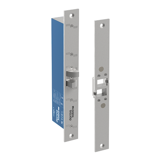
Operating Manual Product description 3 Product description 3.1 View Fig. 1: View Faceplate Housing Double-acting combination latch Connection Strike plate Mounting screws, self-tapping, 10G × 1" csk Screws M5 × 10 Mounting brackets Connection cable 3.2 Accessories (to be ordered separately) •... -
Page 6: Technical Data
Latch position max. 30 V DC max. 100 mA Door position max. 100 V DC max. 500 mA 3.4 Classification dormakaba Deutschland GmbH DORMA Platz 1 58256 Ennepetal Deutschland 0905 – DoPYD30 EN 14846:2008 1 / 3*) *: Fail-safe lock: 1; Fail-secure lock: 3... -
Page 7: Dimensions
Operating Manual Product description 3.5 Dimensions Fig. 2: Lock - dimensions Dimensions lock Dimensions housing (accessories) Dimensions strike plate Dimensions cover plate (accessories) Dimensions of fixing lugs WN 60428 45532/16458 - 08/2022 COBALT Lock SL30DBL... -
Page 8: Operating Modes And Functions
Operating modes and functions Operating Manual 4 Operating modes and functions 4.1 Overview of functions The SL30DBL is a motorized mortise lock for swing doors. Two locking bolts The most striking feature of the SL30DBL is the two counter-rotating locking bolts, which are operated independently of each other. -
Page 9: Mounting
Operating Manual Mounting 5 Mounting 5.1 Requirements for mounting The following aspects must be clarified before installation and connection: • Operating mode • Type of installation • Installation position • Cable routing and wire cross-section Which operating mode? The operating mode is selected to suit the intended use: •... - Page 10 Mounting Operating Manual When installed in the floor, penetrating moisture or similar can contaminate the mechanics of the lock and render the lock unusable in the long term. Cable routing and conductor cross-section The routing and thus the length of the connecting cable must be determined. Three connecting wires are required for the lock to function.
-
Page 11: Example 1: Installing Lock And Strike Plate In Mortise Openings
Operating Manual Mounting 5.2 Example 1: Installing lock and strike plate in mortise openings The installation example describes the installation • of the lock into an insertion opening in the frame, • of the strike plate into an insertion opening in the door. Cut an insertion opening for the lock in the door frame. -
Page 12: Example 2: Install Lock On Frame And Strike Plate On Glass Door
Mounting Operating Manual 5.3 Example 2: Install lock on frame and strike plate on glass door. The installation example describes the installation • of the lock on a wooden frame, • the strike plate on a glass door. Two housings, a cover plate and a long strike plate are required for mounting (accessories). -
Page 13: Electrical Connection
Operating Manual Electrical connection 6 Electrical connection 6.1 Select power supply The lock is designed for low power consumption. Only when the deadbolt is moved does a larger current flow. Select the power supply according to the maximum current consumption. Note: If several locks are connected to one power supply at the same time, the maximum current consumptions of the individual locks are added together. -
Page 14: Connection For Fail-Safe Operation
Electrical connection Operating Manual 6.3 Connection for fail-safe operation Fig. 4: Connection for fail-safe operation Control signal Lock "On" Locked "Off" Unlocked Locking signal Active high ("active-high") Table 2: Function in fail-safe mode 6.4 Connection for fail-secure operation Fig. 5: Connection for fail-secure operation Control signal Lock "On"... -
Page 15: Configure Lock
Operating Manual Electrical connection 6.5 Configure lock Fig. 6: Jumper position Terminal strip Pin header for configuration Jumper for fail-safe operation (delivery state) Jumper for fail-safe operation Next to the connection strip (1) there is a three-pole pin strip which sets the error mode of the lock. -
Page 16: Maintenance
Maintenance Operating Manual 7 Maintenance 7.1 Maintenance and Cleaning The lock has been factory lubricated for life and is maintenance free. The use of other lubricants is not permitted and will void the warranty. This lock contains electromechanical and electronic components that are subject to wear and tear depending on use and on-site installation conditions. -
Page 17: End Of Service Life
• Germany dormakaba Deutschland GmbH will properly dispose of goods delivered at the end of their useful life, in accordance with the legal regulations (ElektroG or the Electrical and Electronic Equipment Act in Germany). Any transport costs incurred are to be borne by the owner of the electronic device. - Page 18 Operating Manual Notes COBALT Lock SL30DBL WN 60428 45532/16458 - 08/2022...
- Page 19 Operating Manual WN 60428 45532/16458 - 08/2022 COBALT Lock SL30DBL...
- Page 20 Deutschland GmbH DORMA Platz 1 58256 Ennepetal Germany Headquarters: +49 2333 793-0 Service DE: 0800 524 0246 www.dormakaba.com www.dormakaba.com...
Need help?
Do you have a question about the COBALT SL30DBL and is the answer not in the manual?
Questions and answers