
Related Manuals for snode SNODEALL9


Summary of Contents for snode SNODEALL9
- Page 1 ALL9 INSTRUCTION MANUAL IMPORTANT: Read all instructions carefully before using this product. Retain this owner’s manual for future reference. The specifications of this product may vary from his photo, subject to change without notice. OWNER’S MANUAL...
- Page 2 STOP. Contact customer service if you have any questions regarding assembly or proper operation of the machine. Email us at: snodefitness@outlook.com Enter into below website to find more innovation products: www.amazon.com/snode Or call us at: Hours: 8:00 am to 5:00 pm (PST) Daily...
-
Page 3: Table Of Contents
TABLE OF CONTENT IMPORTANT SAFETY TIPS EXPLOSION VIEW PARTS LIST ASSEMBLY INSTRUCTION TRAINING INSTRUCTIONS PARTS REQUEST FORM ASSEMBLY INSTRUCTION VIDEO... -
Page 4: Important Safety Tips
Important Safety Tips Please keep this instruction manual for future reference. Although safety precautions have been taken into account as far as possible in the design and manufacture of the training equipment, there are still some safety precautions to be observed in the process of operation, please read the instructionscarefully before assembling and using the training equipment, especially the following safety precautions: 1.Avoid children and pets near the training equipment, and do not let unattended children alone into the... -
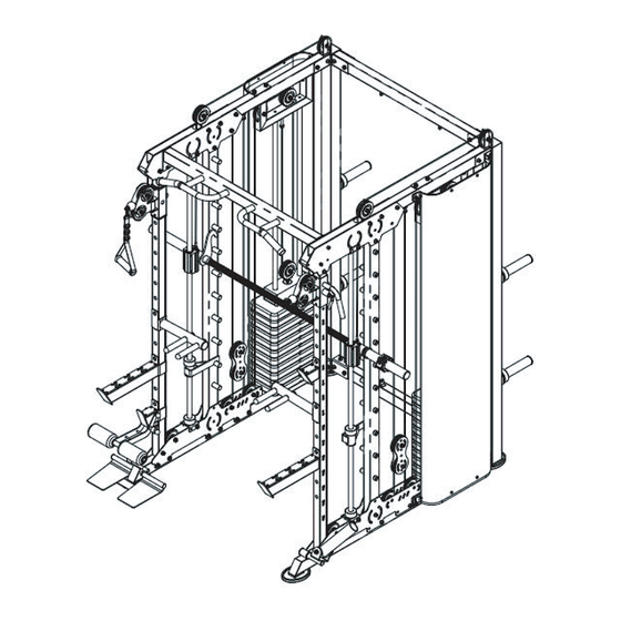
Page 5: Explosion View
EXPLOSION VIEW... -
Page 6: Parts List
PARTS LIST PART NO. Name&Specification 1 PC Left rear riser frame 1 PC Right rear riser frame 2 PCS Rear connecting bracket 1 PC Left bottom bracket 1 PC Upper left top bracket 1 PC Upper right top bracket 4 PCS Bottom connection plate 4 PCS Top connection plate... - Page 7 1 PC Swivel rod bracket 1 PC Swivel rod cover 4 PCS Pulley connection plate 2 PCS Grip Rack 2 PCS Adjustment Rod 4 PCS Connecting hoist piece 22 PCS Hanging bar shaft 22 PCS Barbell locking cap Guide Rod 2 PCS 1 PC Barbell bar assembly...
- Page 8 4 PCS Round tube inner plug ( ) 4 PCS Sleeve 1 PC Right long limiting bracket 1 PC Right double bar rack 1 PC Right short limiting bracket 2 PCS Weight lifting block 28 PCS Pulley ( ) 2 PCS 2 PCS Duct tape 2 PCS...
- Page 9 2 PCS 2 PCS 2 PCS 2 PCS 1 PC 2 PCS 2 PCS Aluminum retainer ring 2 PCS Aluminum head 1 PC Swivel bar bracket 1 PC Swivel bar sleeve 1 PC Footrest 1 PC Limit tube 10 PCS Rubber pad 4 PCS PVC grip sleeve 2...
- Page 10 2 PCS Counterweight Pulley Assembly 2 PCS Weight Adjustment Rod 2 PCS Counterweight head bushing 2 PCS Cylindrical pin 2 PCS M12 hexagonal flange nut 2 PCS Reinforced plate 2 PCS L-shaped pin 2 PCS Counterweight connection frame 1 PC Ball head short pin 2 PCS Cloth mesh...
-
Page 11: Assembly Instruction
ASSEMBLY INSTRUCTIONS STEP 1 Take out the Left rear riser frame (1), Right rear riser frame (2), 2PCS Rear connecting Rear connecting bracket (3) with screws as shown on the figure. - Page 12 ASSEMBLY INSTRUCTIONS STEP 2 Take out 1PC Left bottom bracket (4), 1PC Right bottom bracket (23), 1PC Upper left top bracket (5), Round tube inner plug (103), 1PC Footrest (96), Limit tube (97), Swivel bar bracket (94), Swivel bar sleeve on the Left rear riser frame and Right rear riser frame and lock them tightly, and lock the counterweight guide bar on the Left bottom bracket and Right bottom bracket as shown.
- Page 13 ASSEMBLY INSTRUCTIONS STEP 3 Take out the 2PCS Side riser (9), 4PCS Top connection plate (8), 4PCS Bottom connection plate (7), plate (8) and 4PCS Bottom connection plate (7), respectively, to the Left bottom bracket (4), Right bottom bracket (23), Upper left top bracket (5) and Upper right top bracket (6) with screws as shown on the figure without tightening.
- Page 14 ASSEMBLY INSTRUCTIONS STEP 4 1. Take out the 22PCS Hanging bar shaft (33) and 22PCS Barbell locking cap (34), then lock them on the Side riser (9) respectively according to the diagram and tighten them. 2. Take out the 4PCS Barbell placement fittings (10) and 4PCS Sheath (55), and screw them onto the Left rear riser frame (1) and Right rear riser frame (2) respectively.
- Page 15 ASSEMBLY INSTRUCTIONS STEP 5 1.First, take out Hexagonal nut M16 (104), Lower fixed U-holder (13), 2PCS Vibration-damping washer (48), Safety hanger L (11), Sliding seat (41) and Guide rod (35). As shown in the figure, thread them together from top to bottom and lock with M16 nuts. Then, take out the Upper fixed U-holder (14), lock the Upper fixed assembled Guide bar in the first step on the Bottom connecting plate (7).
- Page 16 ASSEMBLY INSTRUCTIONS U-holder (14), lock the Upper fixed U-holder (14) to the Top connecting plate (8) with 2PCS Hexagonal socket plate (7). STEP 6 Take out the Barbell bar assembly (36), and lock it to the Sliding seat (41) with 8PCS Hexagonal socket...
- Page 17 ASSEMBLY INSTRUCTIONS STEP 7 Take out the Top beam cross-tube bracket (22), 2PCS Slide tube (18), the Left handle adjustment bracket (19), the Right handle adjustment holder (20), 2PCS Pivot pulley rack (21), 8PCS Hexagonal plate (7) and the Top connection plate (8) as shown in the figure, and lock them tightly.
- Page 18 ASSEMBLY INSTRUCTIONS STEP 8 Take out 2PCS Weight lifting block (61), 2PCS Wire rope (86), 4PCS Pulley (62), 4PCS Hexagonal socket block tightly as shown in the figure.
- Page 19 ASSEMBLY INSTRUCTIONS STEP 9 1. Take out 4PCS Vibration-damping washer (48), 22PCS Counterweight (115), 2PCS Counterweight head (114), 2PCS Weight adjustment rod (117), 2PCS Cylindrical pin (119), 2PCS Counterweight head Counterweight pulley assembly (116) and 2PCS L-shaped pin (122). According to the diagram, lock the Vibration-damping washers, Counterweight, Counterweight head, Counterweight pulley assembly on the Weight adjustment rod in order, and insert the L-shaped pins.
- Page 20 ASSEMBLY INSTRUCTIONS STEP 10 Anti-loosening nut (81). Install 2PCS Wire rope (89) on the left and right side to lock tightly as shown in the figure.
- Page 21 ASSEMBLY INSTRUCTIONS STEP 11...
- Page 22 ASSEMBLY INSTRUCTIONS Take out 2PCS Upper fixing sheet for cloth mesh (126), 2PCS Lower fixing sheet for cloth mesh (127), 4PCS Inner compression strips of cloth mesh (128), 8PCS Hexagon socket cylindrical head bolt the top beam and bottom frame tube with the column connecting plate, put the Inner compression strips of cloth mesh into the cloth net both ends of the sewing line folded inside, and then lock it in the corresponding screw hole of the cloth net fixing plate and lock it tightly.
- Page 23 ASSEMBLY INSTRUCTIONS 1. Take out 2PCS Pull strap (66), 2PCS Locking buckle (42), as shown in the figure, connect 2PCS Pull strap (66), 2PCS Locking buckle (42) to the left and right wire rope interface respectively. 2. Take out the Left long limiting bracket and Right long limiting bracket (24, 58), Left double bar rack and Right double bar rack (25, 59), Left short limiting bracket and Right short limiting bracket (26, 61), according to the diagram, put these components on the slide tube.
-
Page 24: Training Instructions
TRAINING INSTRUCTIONS... - Page 25 TRAINING INSTRUCTIONS...
-
Page 26: Parts Request Form
PARTS REQUEST FORM SNODE GROUP, Inc. EMAIL THIS FORM WITH YOUR RECEIPT OF PURCHASE TO snodefitness@outlook.com * NAME: ADDRESS: CITY: STATE: ZIP: TELEPHONE: (Day) (Night) MODEL#: PURCHASE DATE: PLACE OF PURCHASE: PART # DESCRIPTION “YOUR ORDER WILL BE PROCESSED WITHIN 3 BUSINESS DAYS”... -
Page 27: Assembly Instruction Video
ASSEMBLY INSTRUCTION VIDEO Assembly Instruction Video You can scan this QR code to enter into our Youtube page to follow the product assembly videos. Hope it will be helpful for you. Montageanleitung Video Sie können diesen QR-Code scannen, um auf unsere YouTube-Seite zu gelangen,um den Videos zum Produktaufbau zu folgen.
Need help?
Do you have a question about the SNODEALL9 and is the answer not in the manual?
Questions and answers
I have the wrong cables. need help and support.