
Subscribe to Our Youtube Channel
Related Manuals for Extech Instruments IAQ320


Summary of Contents for Extech Instruments IAQ320
- Page 1 USER MANUAL Model IAQ320, Indoor Air Quality Monitor / Datalogger Displays PM , CO , Humidity, Temperature, and Health Index...
- Page 3 Introduction 1.1 Product Overview Thank you for selecting the Extech model IAQ320 air quality monitor. The monitor is easy to use and offers high accuracy, quick response, and intelli- gent operation. In addition to monitoring PM (particulate matter, or dust) and CO...
- Page 4 Safety CAUTION Do not block or obstruct air inlet, air outlet, or ventilation openings, otherwise the meter can overheat. To avoid overheating, disconnect the meter from the power source when not in use. To avoid damage to the meter and injury to persons, use only the supplied AC adapter or a PC USB port to power the meter.
-
Page 5: Meter Power
Meter Power The IAQ320 is powered using the supplied USB cable and AC adapter, as de- scribed below. 1. Connect the supplied USB cable to the meter. The meter’s USB port is lo- cated on its right side. 2. Connect the other end of the USB cable to the supplied AC adapter. Con- nect the adapter to an AC power source. -
Page 6: Product Description
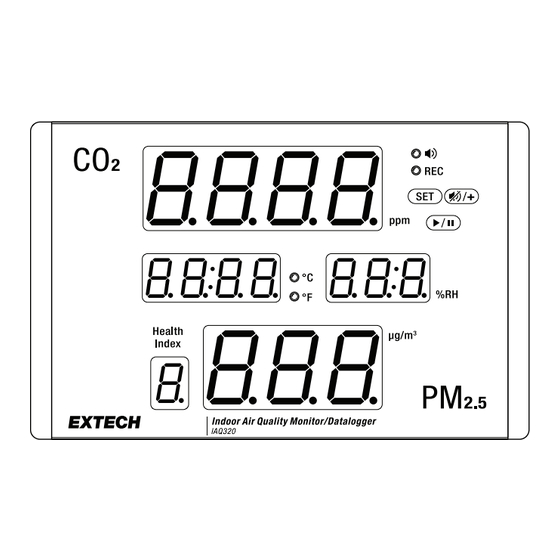
Product Description 4.1 Front Panel 1. CO concentration (0 to 9999 ppm) 2. Ambient temperature 14 to 140℉ (10 to 60℃) 3. Tricolor light bar for CO (green: low, yellow: moderate, red: alarm) 4. Health index (1 to 7) based on 24 hour average 5. - Page 7 Product Description 4.3 Rear Panel 1. Wall-mount holes 2. Air outlet 3. Air inlet with replaceable filter. Loosen the screws to access the filter 4. Reset button (recessed) 5. USB port for meter power and PC interface 6. Tilt stand #NAS100144;...
-
Page 8: Operation
Operation CAUTION The IAQ320 is limited to monitoring air in an approximately 19.8 x 19.8 ft. (6 x 6 m) range. The range varies depending on the height of the room and the contents in the area. For larger areas, an additional meter may be necessary to provide adequate coverage. - Page 9 Operation 5.4 Health Index The Health Index shows PM as a factor (1 to 7). A factor of 1 indicates good air quality; a factor of 7 indicates an extremely hazardous condition. The Health Index is defined by the EPA (Environmental Protection Agency in the US), refer to the table below.
-
Page 10: Settings Menu
Settings Menu 6.1 Settings Menu Overview Long press the SET button to open the menu. In the menu, short press the SET button to step through the options explained below. Press the ‘+’ button to change a setting. If no button is pressed within 25 seconds, the meter will automatically exit the menu. - Page 11 Settings Menu If the ALC 3.0 and 3.1 thresholds are set to the same value, the yellow light bar action is disabled. 6.5 Temperature Units Press the ‘+’ button to toggle the ℃/℉ temperature units. 6.6 Beeper Enable/Disable Press the ‘+’ button to toggle the beeper ON/OFF. 6.7 Pressure Compensation Use the ‘+’...
-
Page 12: Data Logger
Data Logger 7.1 Data Logger Overview The meter can automatically log up to 12,000 readings at an adjustable sam- pling rate. The meter must be powered for 30 minutes before accurate read- ings can be logged. Before logging can begin, the logger must be connected to a PC and configured, using the supplied pop-up configuration window, as explained below. - Page 13 Data Logger 7.3 Configuring the Data Logger Set the options in the Configuration window and click SAVE to prepare for da- ta logging. The numbered list, below, references the numbered items in the accompanying screen shot. 1. Click the Language that will be used for the data log report files. 2.
- Page 14 Data Logger 7.4 Starting/Stopping the Datalogger After configuring the data logger, as explained above, place the meter in the test area and long press the start/stop button to start logging at the pro- grammed rate. The sample rate is set during the configuration process, above. The front panel REC LED will flash while the meter is logging.
-
Page 15: Maintenance
Maintenance 8.1 Cleaning Gently wipe the housing and display using a damp, lint-free cloth. Mild soap can be used, if necessary. Do not use detergents, solvents, or abrasives. 8.2 CO Calibration The meter is factory calibrated to 400 ppm CO concentration. - Page 16 Maintenance • Wide fluctuations in the ambient relative humidity can cause an increase in particle accumulation readings. 8.4 Error Codes The meter will display codes under certain conditions, refer to the table below. CODE DESCRIPTION SOLUTION Sensor damage Return meter for service Under-range in CO mode: Re-calibrate.
-
Page 17: Specifications
Specifications 9.1 Measurement Ranges Measurement Range Resolution 1 ppm 0 to 9999 ppm (parts per million) 0 to 999 µg/m (micro grams per meters cubed) 1 µg/m Ambient temperature 14.0 to 140.0℉ (-10.0 to 60.0℃) 0.1° Relative humidity 0.1 to 99.9% 0.1% Health Index (factor) 1 to 7... - Page 18 Specifications 9.4 General Specifications Meter power Supplied USB cable and universal AC adapter. Compatible with 100 to 240 V AC systems (50/60 Hz) Power consumption < 500 mA Data logger memory 12,000 readings. Transferable to PC via USB connection Operating temperature 32 to 122℉...
-
Page 19: Limited 2-Year Warranty
Limited 2–Year Warranty FLIR Systems, Inc. warrants this Extech brand instrument to be free of defects in parts and workmanship for two (2) years from date of purchase. To view the full warranty, please visit the site below. https://www.extech.com/support/warranties #NAS100144; r. AC/95652/95652; en-US... -
Page 20: Customer Support
Customer Support Customer Support Telephone List https://support.flir.com/contact Repair, Calibration, and Technical Support https://support.flir.com #NAS100144; r. AC/95652/95652; en-US... - Page 22 USER MANUAL last page Website http://www.flir.com Customer support http://support.flir.com Copyright © 2024, FLIR Systems, Inc. All rights reserved worldwide. Disclaimer Specifications subject to change without further notice. Models and accessories subject to regional market considerations. License procedures may apply. Products described herein may be subject to US Export Regulations.
Need help?
Do you have a question about the IAQ320 and is the answer not in the manual?
Questions and answers