Table of Contents
Advertisement
Advertisement
Table of Contents

Related Manuals for Extech Instruments Extech 380976


Summary of Contents for Extech Instruments Extech 380976
- Page 1 User Guide 1Φ/3Φ 1000 Amp True RMS Power Clamp-On Model 380976...
-
Page 2: Table Of Contents
Introduction Congratulations on your purchase of the Extech 380976 Power Clamp-On Meter. This device measures 1Φ/3Φ Power (True, Apparent, and Reactive), Horsepower, Phase Angle, True RMS Current/Voltage, Resistance, Capacitance, Frequency, & Temperature. Power measurements can be achieved on 3- or 4-wire configurations. Please read the entire manual to get the most from the meter’s wide array of capabilities. -
Page 3: Warranty
• Before taking resistance measurements or testing continuity, disconnect the circuit under test from the main power supply and remove all loads from the circuit. Safety symbols Caution! Refer to this manual before using the meter. -
Page 4: Meter Description
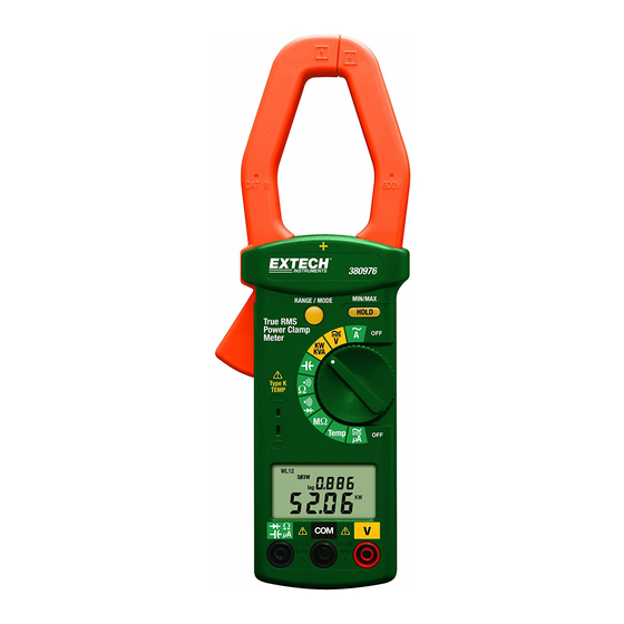
Meter Description Transformer Jaws Jaw opening trigger Data Hold & MX/MN button Function Selector Range button Temperature input jack LCD Display ‘COM’ input jack ‘V’ input jack µA Ω input jack 380976 V3.2 4/11... -
Page 5: Ac + Dc Voltage Measurements
Measurements AC + DC Voltage Measurements The maximum input is 600V. Do no attempt voltage measurements above this limit. Exceeding this limit could cause electrical shock and damage to the meter. 1. Set the rotary switch to the ‘ 2. Insert the test leads into the meter’s input jacks. (Black to ‘COM’... -
Page 6: Kw, Kva, Kvar, Power Factor & Phase Angle Measurement
NOTES 1. The ‘+’ sign printed on the meter must face the power source for best accuracy. 2. If the device under test is a switching mode power supply, the KW, PF, and Phase angle measurements may not be accurate. -
Page 7: 3-Wire Kw, Hp, Kva, Kvar, Power Factor & Phase Angle Measurement
1. First, measure W (refer to the diagram below). RS(L1L2) Set the rotary switch to the “ Press and hold the “HOLD” key while setting the rotary switch to “KW/KVA”, the 3φ3W and symbols will appear. Insert the test leads into the jacks. Select a phase (e.g. - Page 8 4. To read a single data record, press the “HOLD” key to select desired W display then press the “RANGE” key to select KW+HP (Horse Power), KW+PF (Power Factor), KW+KVAR, KVA+ θ (Phase Angle) or A+V.
- Page 9 1. The "+" sign printed on Panel must face the power source for accurate measurement. 2. If the device under test is a switching power supply, the meter KW, PF and θ reading maybe incorrect. For 3 φ 3W unbalanced power measurements, W RS or W TS could be negative.
-
Page 10: 4-Wire Kw, Hp, Kva, Kvar, Power Factor & Phase Angle Measurement
1. First, measure W (refer to the diagram below). R(L1) Set the rotary switch to the “ Press and hold the “RANGE” key while setting the rotary switch to the “KW/KVA” position, the 3φ4W and W symbols should appear. Insert the test leads into the input jacks. Connect the neutral line to the COM (black) terminal. - Page 11 3. Third, measure W T(L3) (refer to the diagram that follows the steps below) Disconnect the test probe from the phase where the jaws were clamped in the previous measurement. Connect the test probe of the V (red) terminal to the third phase (e.g. T or L3 phase). Clamp the phase where the test probe is connected to (e.g.
- Page 12 The 3 φ 4W power value in watts is now stored in the meter’s memory. 5. To read a single data record, use the “HOLD” key to select WL1, WL2, WL3 or WL123 display then press the “RANGE” key to select KW+HP (Horse Power), KW+PF (Power Factor), 380976 V3.2 4/11...
-
Page 13: Resistance And Audible Continuity Measurements
1. The "+" sign printed on meter must face the power source for accurate measurement. 2. If the device under test is switching power supply, the KW, PF and θ readings may not be correct. For 3 φ 4W power measurements, W negative power, check the connections. -
Page 14: Capacitance Measurements
1. Fully discharge the capacitor under test before proceeding. 2. Insert the test leads into the input jacks. (Black to ‘COM’ and Red to ‘ ’). 3. Set the rotary switch to the ‘ 4. Connect the red and black test leads to the capacitor. For Electrolytic (polarized) capacitors, connect the red test lead to the positive side and the black lead to the negative side. -
Page 15: Meter Control Keys
Meter Control Keys HOLD - MX/MN Key Data Hold Function Press this key momentarily to put the meter into Data Hold mode (HOLD will appear on the LCD). In this mode, the meter freezes the displayed reading. To exit the Data Hold mode, press the key again (the HOLD icon will switch off). -
Page 16: Automatic Sleep Mode And Battery Replacement
Automatic Sleep Mode and Battery Replacement The Meter is powered by a 9V battery. An AUTO SLEEP feature is included to preserve battery life. Note: The Auto Power OFF feature is disabled when the meter is in the MIN/MAX mode Note: In the sleep mode the meter continues to draw a small amount of battery current. -
Page 17: Specifications
Specifications General Specifications Display Jaw Opening Max. Input limit Sampling rate Auto Sleep Low battery indication Power supply Battery life Operating Temperature Operating Humidity Operating Altitude Storage Temperature Storage Humidity Temperature coefficient Dimensions Weight Approvals Safety UL Listed PER IEC1010 OVERVOLTAGE INSTALLATION CATEGORY... - Page 18 Accuracy: ± (% of rdg + number of digits) from 18 AC Current (50Hz to 400Hz) True RMS Range Resolution Accuracy (% reading) 99.99A 10mA ± (2% + 20d) (50, 60Hz) ± (4% + 20d) (40~400Hz) 999.9A 100mA μA True RMS (AC+DC) Range Resolution 10nA...
- Page 19 C to 900 F to 1000 1Φ/3Φ TRUE Power (PF > 0.5 or Range 60.00KW (<100A) 600.0KW (>100A) 1Φ/3Φ Horse Power (HP) (PF > 0.5 or Range Resolution 80.00HP (<100A) 800.0 HP (>100A) 1Φ/3Φ Reactive Power (KVAR) (PF > 0.5 or Range 60.00KVAR (<100A)
-
Page 20: Calibration, Repair, And Technical Support Services
1Φ/3Φ Apparent Power (KVA) Range 60.00KVA (<100A) 600.0KVA (>100A) Phase Angle (50/60Hz) Range -60° ~ 0° ~ +60° Frequency Range 40Hz/1KHz Calibration and Repair Services Extech offers repair and calibration services for the products we sell. Extech also provides NIST certification for most products.
Need help?
Do you have a question about the Extech 380976 and is the answer not in the manual?
Questions and answers