Table of Contents
Advertisement
Quick Links
PS-7-M series
Extractive Pump Gas Detector
(detachable sensor/sampling units)
Instruction Manual
Keep this manual for easy reference.
Carefully read this manual prior to use.
This manual describes the standard model. If your unit has end-user-specific options, this
manual will be superseded by your delivery specifications.
Instruction Manual No.
GAE-138-00
Feb 2019
Advertisement
Table of Contents

Related Manuals for New Cosmos Electric PS-7-M Series


Summary of Contents for New Cosmos Electric PS-7-M Series
- Page 1 PS-7-M series Extractive Pump Gas Detector (detachable sensor/sampling units) Instruction Manual Keep this manual for easy reference. Carefully read this manual prior to use. This manual describes the standard model. If your unit has end-user-specific options, this manual will be superseded by your delivery specifications.
- Page 2 Unit Dimensions and Sensor Unit Components Installation/Replacement 5. “Unit Dimensions and Components” 9-2. “Sensor Unit Installation on page 6. /Replacement” on page 41. Base Unit installation/Wiring Operation 6. “Installation and Wiring” on page 12. 7-1. “Operation” on page 19. For checking normal operation, refer to page 30.
-
Page 3: Table Of Contents
Table of Contents 1. Introduction ......................- 1 - 1-1. Manuals and related documents ..............- 1 - 1-2. Overview ......................- 2 - 2. General Precautions ..................... - 3 - 3. Package Contents....................- 4 - 4. Block Diagram ...................... - 5 - 5. -
Page 4: Introduction
1-1. Manuals and related documents The following documents are prepared for use of this product. 1. PS-7-M series gas detector’s instruction manual (This document, Doc.No.GAE-138-xx) This document provides the following information to ensure safe use of this product. Safety precautions ... -
Page 5: Overview
PS-7-M series gas detectors are divided into three models according to the sensor unit type and with/without a pyrolyzer. For sensor selection, please contact New Cosmos or its authorized representative. -
Page 6: General Precautions
2. General Precautions Carefully read this manual prior to use. To ensure safe operation, follow the precautions below. Wiring and installation should only be performed by a qualified electrician with knowledge of wiring/installation procedures. This product is not explosion-proof equipment and should not be installed in a hazardous area. -
Page 7: Package Contents
3. Package Contents The following items are included in a standard package. If any items are missing or damaged, please contact New Cosmos or its authorized representative for replacement. Table 1. Standard contents Item Name Qty. Gas detector (PS-7-M) Half union (male connector) R1/4- ø6mm or R1/4- ø1/4 in. -
Page 8: Block Diagram
4. Block Diagram MF-50 (filter unit) Sampling unit Sensor Pump Gas in Gas out Rc 1/4 Rc 1/4 Flow seneor GAS IN Rc 1/4 Controller COMM RJ-45 PoE power board Ethernet signal Main unit PW SW Power 24 VDC CPU board Analog output 4-20mADC Earth terminal... -
Page 9: Unit Dimensions And Components
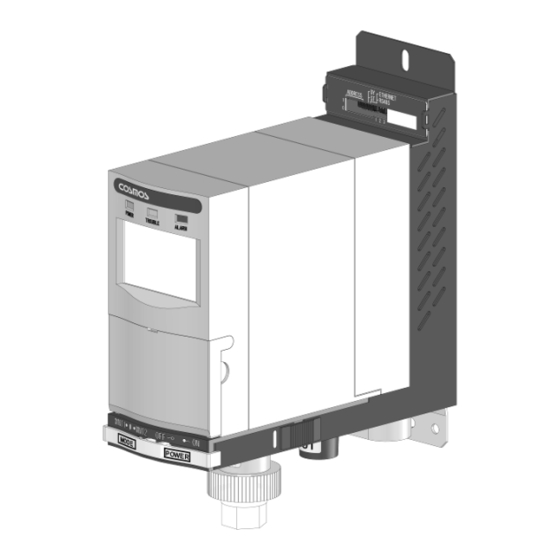
5. Unit Dimensions and Components 5-1. Exterior Appearance PS-7-M-01/02 Mounting pitch: PS-7-M-03 (Dimensions are in mm) Item Component Description/Function Main unit Includes a display, a pump and a sensor. Thread cables thru the cable entry hole on the bottom of the base Base unit unit and connect to the main unit Incorporates a filter element (FE-1) that prevents dust from entering... -
Page 10: Main Unit
5-2. Main Unit (Dimensions are in mm) Item Component Description/Function When lit, the unit is in normal operation mode Green POWER LED (gas-monitoring mode). Amber TROUBLE LED Flashing indicates an internal failure is present. Red ALARM LED Flashing indicates a gas alarm is present. Displays alarm notification, numeric gas concentration value, gas concentration on bar graph, trouble status, maintenance/test mode, and flow rate status. -
Page 11: Base Unit
5-3. Base Unit Item Component Description/Function Fuse Internal circuit protection. Base unit power switch Turns on/off the base unit. φ5.5 mm Mounting hole Terminal block (2 places) Used for external wiring. Turns on/off the main unit. Note: If the base unit power Main unit power switch switch is off, no power is supplied to the main unit. -
Page 12: Dip Switches
5-4. DIP Switches Set the base unit power switch to the OFF position before using the DIP switches to avoid incorrect operation or device failure. Do not use IP address “255 (1111 1111)” because LAN Communication will be disabled if that IP address is used. -
Page 13: Operation Buttons
5-5. Operation Buttons Opening front cover Pull and slide down the front cover to access the operation buttons and TEST switch. Front cover Slide down Pull open Panel Item Component Description/Function marking SPAN button Performs span adjustment. For O2 sensor unit SPAN (Span adj. -
Page 14: Lcd Indicator Icons
5-6. LCD Indicator Icons Item Icon/Display Description/Function Displays gas concentration and the unit of measurement. Numeric display E.g. %LEL, ppb, ppm FLOW Flow rate is low. Linked with item 6. ALARM1 ALARM2 and 2 stage gas alarms. A sensor fault (e.g. broken wire) is present or incorrect SENS. -
Page 15: Installation And Wiring
6. Installation and Wiring This product is not explosion-proof equipment and should not be installed in a hazardous area. For detection of adsorptive gas (e.g. HF and F2), remove the filter element (FE-1) from the filter unit (MF-50). Correct detection is not possible if the filter element is present. Refer to 9-1. -
Page 16: Wiring Procedure
When installing the gas detector, ensure there is enough space NOTE below/above the detector to allow for installation/removal/wiring activities. (Recommended: More than 100mm above the unit and 150mm below the unit.) When installing more than one detector side by side, make sure to leave enough space right and left to the gas detector to allow for installation/removal of the main unit. - Page 17 Marking Polarity Function * Recommended cable * on board Power input (24 VDC) 2-core CVV cable Gas concentration output (4-20 mADC) 3-core CVVS cable Earth terminal Trouble alarm (Open collector: N.C.) 2-core CVV cable Max. load: 30 VDC, 30mA resistive load Trouble alarm, Common 2-core shielded twisted pair cable...
-
Page 18: Modbus Tcp (Ethernet) Wiring Procedure
6-1-1 Modbus TCP (Ethernet) Wiring Procedure Establishing Modbus TCP communication When using the 24 VDC power supply, ensure that the power is 24 VDC 10%. When using the PoE power supply, ensure that the LAN cable is securely connected. When PoE-HUB is connected, (1) Insert a LAN cable to the RJ-45 jack located at the bottom of the base unit. - Page 19 (1) Run a power cable thru the grommet (located at the bottom of the base unit), and connect the cable wires to their corresponding terminals (refer to “Terminal layout” on page 14). (2) Run a RS-485 digital signal cable thru the Terminal Terminal grommet (located at the bottom of the base unit),...
-
Page 20: Unit Installation Procedure
6-2. Unit Installation Procedure Determine where to place the base unit (positioning). Secure the mounting plate to the wall with the two mounting screws (M4x8). Anchor the base unit to the mounting plate by inserting the mounting plate into the slot on bottom of the base unit, and secure using the mounting screw (M4x8). -
Page 21: Tube Fitting Connection Procedure
6-3. Tube Fitting Connection Procedure Install the provided half union tube fitting into the filter unit inlet and gas outlet. Over tightening the filter unit inlet may break the gas inlet. When connecting the provided half union to the filter unit inlet, secure the filter unit inlet with one adjustable wrench or spanner, etc. -
Page 22: Operation
7. Operation 7-1.Operation Procedure Operation Flow Corresponding numbered steps are given for items1 to 13 on the following pages. Initial startup 1. Set the IP address/Unit PW 24 VDC Select the power supply. Disconnect and Check the power 2. - Page 23 Operation Steps Operate the gas detector by taking the following steps. When using the 24 VDC power supply, ensure that the power is 24 VDC 10%. When using the PoE power supply, ensure that the LAN cable is securely connected. ...
- Page 24 The IP address settable range is 1 (0000 0001) to 254 (1111 1110). NOTE When the IP address is “0 (0000 0000)”, it will be superseded by the IP address set by a web browser. Refer to "PS-7-M IP address setting guide” (separate document) for IP address change ...
- Page 25 Set the base unit power switch to the ON position. Base unit power switch Power ON Adjust the analog output for the maintenance mode 2 (MNT2). The maintenance mode 2 analog output varies depending on the sensor unit type. Therefore, the output needs to be adjusted by taking the following steps.
- Page 26 Trimmer (adjustment screw) Rotate the trimmer with a slotted screwdriver to adjust the MNT2 output level. H NOTE Toxic gas sensor (CDS-7) Oxygen sensor Oxygen sensor (COS-7, FS: 25vol%) (COS-7, FS: 50vol%) Combustible gas sensor (CHS-7) Analog output Analog output O2 level O2 level...
- Page 27 Set the main unit power switch to the ON position. To ON position Lift the cover flap open. Main unit power switch All the LEDs on the front and the LCD turn on for one second, then the gas detector starts self-test.
- Page 28 10. Check the set values. Note: To change the set values, refer to the “PS-7 gas detector’s operation manual for administrators” (separate document). To view the set values shown in the table below, press the UP/DOWN button. Press the UP/DOWN button to cycle through the items in the sequence shown in the table. The set value for the selected item is displayed on the sub-display (bottom right).
- Page 29 To view each gas alarm set value, press the AL button. Press the AL button to cycle through the items in the sequence shown below. A1 ** A2 ** (normal operation mode) A1 ** A2 ** The percentage in full-scale% is shown on the sub-display (bottom right corner).
- Page 30 NOTE Clogging notification Slowly spinning The flow rate icon slowly spins when the flow rate is reduced (less than 400mL/min), indicating a possible clogged tube/filter, or excessive negative pressure, etc. Gas detection and gas-monitoring continue even when this gas notification is present. Stops spinning Low flow rate alarm notification When the flow rate is too low (300mL/min or less), the flow...
- Page 31 13. One-touch zero/21vol% adjustment (Zero adjustment for CDS-7, CHS-7 and 21vol% adjustment for COS-7) Take the steps in the table below, to perform one-touch zero/21vol% adjustment once the specified period of time passes after turning on the main unit. Repeat the one-touch zero/21vol% adjustment to increase the accuracy.
- Page 32 Toxic gas sensor (CDS-7) Oxygen sensor (COS-7) Combustible gas sensor (CHS-7) Press the ZERO button for more than 2 Press the SPAN button for more than 4 seconds. The green POWER LED will seconds. The green POWER LED will flash one time, indicating the zero flash one time, indicating the zero adjustment is completed.
-
Page 33: Operation - Gas Alarm
Normal Trouble alarm stage stage operation(gas (internal failure) gas alarm gas alarm monitoring) Green lit Amber flash Red flash Red flash FLOW ALARM1 SENS. ALARM1 ALARM2 CONV. Gas alarm contact (ZA1) (open position) (open position) (closed position) (closed position) Gas alarm contact (ZA2) (open position) (open position) - Page 34 Green Amber On display POWER LED TROUBLE LED ALARM LED stage gas alarm ALARM 1 Flashing ALARM 1 stage gas alarm Flashing ALARM 2 A1 and A2 relation in each gas alarm mode NOTE H - H mode (High-High limit alarm) Full scale stage gas alarm: ALARM1 and ALARM2 are lit.
-
Page 35: Operation - Trouble Alarm
7-3. Operation - Trouble Alarm This unit can detect an internal failure. When an internal failure is detected, a trouble alarm will activate (open collector is normally ON (closed position) and during a trouble alarm switches to OFF (open position). The amber TROUBLE LED will start flashing, and the analog output will fall to 0.6mA or less. - Page 36 Oxygen sensor (COS-7): The analog output from this product falls to 0.6mA or less in the event of a trouble alarm as listed above. When the host system (e.g. control room) is set to the low limit alarm (gas alarm activates when the gas concentration falls to the alarm set value or less) and If the product’s analog output falls to 0.6mA or less in under a second without a gas alarm, then it means that a trouble alarm is present.
-
Page 37: Operation - Test Mode
7-4. Operation - Test Mode Setting Press the TEST switch with the test stick to enter the test mode. Each press of the recessed TEST switch will turn on and off the test mode. The test mode will automatically end in10 minutes. Increase/decrease the analog output value using UP/DOWN button. -
Page 38: Operation - Maintenance Mode
7-5. Operation - Maintenance Mode Setting The maintenance switch has three modes, maintenance mode 1 (MNT1), maintenance mode 2 (MNT2), and normal operation mode (gas monitoring mode). Set the maintenance switch to MNT1 or MNT2 on the base unit’s front. “MNT1” or “MNT2” will be shown on the LCD. - Page 39 While in maintenance mode, the status information of gas/trouble alarms is sent to the host system (e.g. control room) digitally. If the gas alarm contacts/trouble alarm open collector are used to operate the interlocks of the external devices, release the interlocks beforehand, as needed to prevent a possible activation of the interlocks during the maintenance mode.
-
Page 40: Maintenance
8. Maintenance This gas detector requires no on site gas calibration. Each sensor unit has been gas-calibrated when shipped. Replace the sensor unit with a new one every 6 months except for combustible gas sensor units (CHS-7). The CHS-7 is divided into two types, hot-wire combustible (CH) and catalytic (CS). - Page 41 (1) Concentration display Check that the gas concentration value is shown on the LCD and the detector is operating. Green POWER LED is on. Amber TROUBLE LED is off. Red ALARM LED is off. Gas concentration with unit of measurement (%LEL, ppb, or ppm) Flow rate icon quickly spins.
- Page 42 (7) Sampling unit replacement Replace the sampling unit with a new one every 3 years. For procedure, refer to 9-3. “Sampling Unit Replacement”. (8) Loop check and alarm test using TEST switch Press the TEST switch with the test stick to send a pre-set analog output to the host system. Check the output at the host system.
-
Page 43: Consumable Parts Replacement
9. Consumable Parts Replacement This product has been designed so that its consumable parts can be easily replaced by the end user. Contact New Cosmos or its authorized representative for ordering. 9-1. Filter Element Replacement If the filter element (FE-1) is dirty, replace it with a new one by taking the following steps. 1. -
Page 44: Sensor Unit Installation/Replacement
9-2. Sensor Unit Installation/Replacement Check that the target gas type and full scale value are correct before using a new sensor unit. Also, check that the sensor unit expiration date has not been reached. Note: The expiration year/month is not indicated on combustible gas sensor (CHS-7). CHS-7 is divided into two types, hot-wire combustible (CH) and catalytic (CS). - Page 45 3. Press the top of the rear cover with thumb and tip the rear cover back to separate the rear cover from the main unit. Press here then pull back the rear cover. 4. Insert a finger between the main unit and the sensor unit so that the sensor unit tilts forward slightly.
- Page 46 6. Pull forward and hold the latches at both sides and connect the main unit by sliding it onto the rails of the base unit. (2) Align with the rail and slide on. Rail (1) Pull forward and hold the latches at both sides. 7.
-
Page 47: Sampling Unit Replacement
9-3. Sampling Unit Replacement Turn off the gas detector prior to sampling unit replacement. Setting the main unit power switch to the OFF position will turn off the trouble alarm output (open collector). If the trouble alarm output is used to operate the interlocks of the external devices, release the interlocks beforehand, as needed, to prevent a possible activation of the interlocks during replacement. - Page 48 4. Connect the two connectors. Mate the sampling unit and front panel. Insert the sensor unit. Install the rear cover. Front panel Rear cover Ensure cables are not caught If the sensor unit is not completely inserted, an airtight seal will not be created, and correct gas detection will not be possible.
-
Page 49: Troubleshooting
10. Troubleshooting Before requesting repair, please refer to the table below. If the detector does not return to normal operation after performing the corresponding steps in the table, or if your issue is not found in the table, consult New Cosmos or its authorized representative. ... - Page 50 Problem Probable cause Steps Reference section Set the maintenance Gas concentration Maintenance switch switch to the center 7-5. Operation - value and ”_ _ _ _” is set to MNT1 or position (normal Maintenance Mode flashing alternately. MNT2. operation mode). Set the maintenance Maintenance switch switch to the center...
-
Page 51: Specifications
11. Specifications Detection principle Electrochemical with/without pyrolyzer, Hot-wire semiconductor, Catalytic, or Galvanic cell Sampling method Extractive pump (500mL/min. auto-controlled) Sampling tube PTFE, Outside and inside dia.: 6mm and 4mm (or 1/4 in. and 11/64 in.) Piping length: < 20m Target gas As per delivery specifications Detection range As per delivery specifications... - Page 52 Gas alarm contacts (1 and 2 stages) N.O. dry contact (same common), self-resetting Max. load: 30 VDC, 0.5A (resistive load) Trouble alarm open collector N.C. self-resetting Turns off (open position) in the event of low flow rate, sensor fault, incorrect sensor installed, or broken pyrolyzer wire, no power, or blown fuse.
-
Page 53: Warranty
recommended material. Specify 1/4 in. 11/64 in. outside and inside diameter during order placement if the standard 6mm and 4mm outside and inside diameter tubing will not be used. *2. For adsorbable gas (e.g. HF, F2, HCl, Cl2, NH3), use of less than 5m length piping is recommended. When using this product in a place exposed to dust, the piping may need to be shorter than recommended and periodiAbocally replaced. -
Page 54: Detection Principle
15. Detection Principle 15-1. Electrochemical Sensor (CDS-7) This sensor consists of three electrodes and an electrolyte, and the method adopted here is to produce electrolytic oxidation with a potentiostat circuit while keeping the working electrode at a constant potential against the reference electrode. Measuring the current generated here allows determining the concentration of the gas (e.g. -
Page 55: Glossary
16. Glossary Term Definition Gas detector Device used to detect the presence of a target gas and to give its concentration in the form of an electrical signal. Enclosure in which the parts which can ignite an explosive Flameproof enclosure atmosphere are placed. - Page 56 Revision GAE-138-00 Feb 2019 (Initial issue) Additional copies of this instruction manual may be purchased. Contact New Cosmos or its authorized representative for ordering. Authorized representative: Manufacturer: NEW COSMOS ELECTRIC CO., LTD. 2-5-4 Mitsuya-naka, Yodogawa-ku Osaka 532-0036, Japan URL: http://www.new-cosmos.co.jp...
Need help?
Do you have a question about the PS-7-M Series and is the answer not in the manual?
Questions and answers