Advertisement
Genuine Part Number:
Applicable Model:
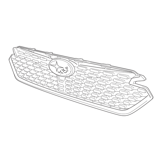
Thank you for purchasing the Subaru Genuine Sport Grille.
This manual describes the procedure to install the Sport Grille onto the Impreza.
Be sure to read this manual before installing the product, and correctly install the product according to the instruc ons.
Component Parts
GG299–04070
Sport Grille
J1010FN510
IMPREZA (2024+)
Installation Manual
Sport Grille
No.
Part Name
Sport Grille
Camera Cover
Screw M4, 12 mm
△ 00
Qty
1
1
2
1
Advertisement
Table of Contents

Related Manuals for Subaru J1010FN510


Summary of Contents for Subaru J1010FN510
- Page 1 Applicable Model: IMPREZA (2024+) Thank you for purchasing the Subaru Genuine Sport Grille. This manual describes the procedure to install the Sport Grille onto the Impreza. Be sure to read this manual before installing the product, and correctly install the product according to the instruc ons.
- Page 2 Installa on Precau ons For your safety, important instruc ons that should be observed are denoted by the following symbols in this manual. CAUTION ……This symbol denotes a risk of danger that may cause bodily injury or property damage if the precau on is disregarded. ……This symbol provides ps you should be aware of so that you can easily and quickly install the product.
-
Page 3: Installation Procedure
Product after Installation Sport Grille Installation Procedure 1. Removing the Air Intake Duct ⑴ Remove the two plastic clips, and detach the air intake duct from the vehicle. Plastic Clip × 2 CAUTION The removed vehicle parts will be reused, so be careful not to misplace them. (Do the same Air Intake Duct throughout the rest of the procedure) TG-BZ-A06... -
Page 4: Removing The Front Upper Cover
2. Removing the Front Upper Cover Plastic Clip × 3 ⑴ Remove the three plastic clips, and detach the cover. Front Upper Cover TG-BZ-A07 3. Applying Protective Tape ⑴ Apply protective tape to the shaded area as shown in the illustration. ⑵ Perform the same for the other side. Protective Tape TG-BZ-A01 4. Removing the Front Bumper Fender Liner ⑴ Remove the plastic clip A from the four locations and clip B from the one location in order to unfasten the front bumper, and create an opening by partially detaching the front bumper and fender liner so that your hand can access the fog light. - Page 5 < Vehicles equipped with headlight washers > <Vehicles equipped with headlight washers> ⑸ Pull out the headlight washer nozzle LH, Top View disengage the claw, and detach the cover. Flat-head Screwdriver Claw ⑹ Perform the same for the other side. Protective Tape Cover Headlight Washer Nozzle LH TG-BZ-A03 < All models > ⑺ Remove the following components from the top Plastic Clip B × 4 of the front bumper: Six bolts, Two plastic clip A, Bolt ×...
- Page 6 ⑼ Disengage the 12 claws (left and right, six claws Camera Wire Harness Connector respectively), and remove the front bumper. (if equipped) CAUTION ⑴ In order to prevent the removed front bumper from being damaged, place and store it on protective sheets or blankets. ⑵ For vehicles equipped with a camera, be sure to disconnect the camera wire harness. Claw × 6 (same for the other side) Front Bumper TG-BZ-A05 5. Removing the Front Grille from the Bumper Front Bumper Screw × 6 ⑴...
- Page 7 6. Installing the Camera or Camera Cover < Vehicles without a camera > < Vehicles without a camera > < Vehicles without a camera > Screw×2 Screw×2 ⑴ Install the camera cover included in the package to the Sport Grille with the two new screws and one guide. Tightening torque: 1.1 N ・ m ±0.2 (10 in-lbs ±1) Guide Guide Camera Cover...
- Page 8 ⑵ Fasten the top of the front bumper with the following components: Six bolts, Two plastic clip A, and Four plastic clip B. Plastic Clip B × 4 ⑶ Fasten the bottom of the front bumper with the Bolt × 6 plastic clip B at the eight locations. Plastic Clip A × 2 Tightening torque: 7.5 Nꞏm (0.8kgf-m, 5.5ft-lb) Plastic Clip B × 8 Front Bumper TG-BZ-C02 < Vehicles equipped with headlight washers > <Vehicles equipped with headlight washers>...
- Page 9 < Vehicles equipped with fog lights and sensors > Fender Liner ⑹ Create an opening by partially detaching the front bumper and fender liner so that your hand can access the fog light, and reconnect both fog light connector LH and sensor connector LH. ⑺ Perform the same for the other side. CAUTION ⑴ Be extremely careful not to injure your hands or arms when reconnecting the connectors. Front Bumper Plastic Clip A × 4 ⑵ Confirm the orientation of the fog light connector, and securely connect it until a Plastic Clip B click sound can be heard. Failure to do so may <Vehicles equipped with fog lights and sensors> cause the fog light to remain off due to poor connector connection.
-
Page 10: Inspection After Installation
Inspection after Installation ⑴ Remove all the protective tape. ⑵ Follow the instructions in the service manual. ⑶ For vehicles equipped the the multi-view monitor system, calibration is required. Refer to the service manual for the instructions on how to calibrate the system, and carry out the calibration. CAUTION ⑴ Check that the fog lights come on and stay illuminated. ⑵ Check that camera views are correctly shown on the multifunction display. ⑶ Double-check that the plastic clips, bolts or parts are not loose. Revision History Version Summary of Changes Revision Date △00 Original version January 2023...
Need help?
Do you have a question about the J1010FN510 and is the answer not in the manual?
Questions and answers