Table of Contents
Advertisement
Quick Links
Genuine Part Number
Applicable Model
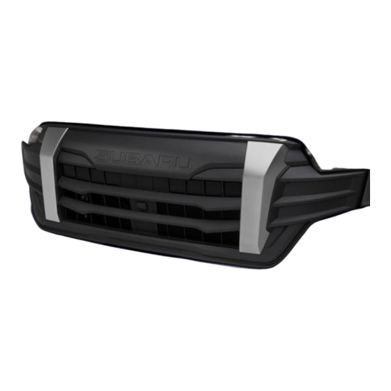
Thank you for purchasing the Subaru Genuine Sport Grille.
This manual describes the procedure to install the Sport Grille on the FORESTER.
Be sure to read this manual before installing this product and follow the instructions described below.
Component Parts
GG219–02670
Sport Grille
J1010SL000
FORESTER 2025MY~
Installation Manual
Sport Grille
No.
Part Name
Sport Grille
Camera Cover
Screws #4 × 12 mm
△ 00
Quantity
1
1
2
1
Advertisement
Table of Contents

Subscribe to Our Youtube Channel
Related Manuals for Subaru J1010SL000


Summary of Contents for Subaru J1010SL000
- Page 1 △ 00 Sport Grille Installation Manual Genuine Part Number J1010SL000 Applicable Model FORESTER 2025MY~ Thank you for purchasing the Subaru Genuine Sport Grille. This manual describes the procedure to install the Sport Grille on the FORESTER. Be sure to read this manual before installing this product and follow the instructions described below. Component Parts Sport Grille Part Name Quantity Sport Grille Camera Cover Screws #4 × 12 mm GG219–02670...
-
Page 2: Installation Precautions
Installation Precautions For your safety, important instructions that should be observed are shown with the following symbols in this Installation Manual. CAUTION ……This refers to situations in which injury may occur or property may be damaged if the caution instructions are not followed. N O T E ……This denotes things that you should be made aware of so you can do the work quickly. ⑴ Park the vehicle on a level place, apply the parking brake, and use wheel chocks. ⑵ Make sure to arrange vehicle parts by part when removing them so that you do not lose the tapping screws, nuts and bolts, and so you do not mistaken them when reinstalling the vehicle components. Also, pay due attention not to damage the vehicle and the removed parts during work. ⑶ Follow the Service Manual when handling the battery. ⑷ To prevent damage to the vehicle and vehicle parts when removing vehicle parts and installing the product, be sure to perform the work on a Protective Sheet. Installation of Parts After Completion of Installation ●Pay attention to the back side and do not allow ●Use the proper size of tools. ●Be sure to reassemble all the vehicle parts that any wire harness to get caught. have been removed. Clicks CAUTION Follow the Service Manual when performing the work. Tools Required Philips screwdriver, Flat head screwdriver, Torque check screwdriver, clip removal tool, Needle nose pliers, Protection tape, Waste cloth, De-greasing agent... -
Page 3: Installation Procedure
Post-installation Diagram Sport Grille Installation Procedure 1. Applying Protective Tape The figure shows the left side. ⑴ Apply Protective Tape to the shaded area Protective Tape in the figure. ⑵ Repeat the same procedure for the right side. Protective Tape Protective Tape TG-CT-A01... - Page 4 2. Detaching the Camera Harness Camera Harness <For vehicles with a camera> ⑴ Disconnect the Connector on the Camera Harness. Connector TG-CT-A06 3. Removing the Front Bumper The figure shows the left side. ⑴ Pull out the Headlamp Washer Nozzle, Flathead Screwdriver Headlamp Washer Nozzle Claw disengage the Claw, and remove the cover. ⑵ Repeat the same procedure for the right side. CAUTION Protective Tape Unless otherwise stated, the removed vehicle parts will be reused, so be careful not to misplace them. (Adopt this practice Cover throughout the rest of the procedure) Cover TG-CT-A02 ⑶ Remove Plastic Clips A (4 pcs) that secure...
- Page 5 ⑸ Disengage Clips (3 places) and Claws The figure shows the left side. Clip x 3 (4 places) and allow Fender Moulding to rise up on front side of vehicle. Fender Moulding N O T E If Clips remain on vehicle, remove them using a Clip Remover, etc. and attach to Fender Claw Cross-section Push Moulding before restoring to original position. Claw x 4 ⑹ Repeat the same procedure for the right side. Front Bumper TG-CT-A08 ⑺ Remove Bolt (1 pc) and Plastic Clips (15 pcs). Bolt Front Bumper Plastic Clip B x 15 TG-CT-A04 ⑻ Pull back the Mudguard and disconnect the The figure shows the left side. Fog Lamp Connector. ⑼ Repeat the same procedure for the right side. Mudguard Pull back Fog Lamp Connector TG-CT-A07...
-
Page 6: Removing The Camera
⑽ Disengage the Claws (18 places) and remove Claw x 9 the Front Bumper. (same on RH side) CAUTION ⑴ Be careful not to break the harness when removing the Front Bumper. ⑵ Place the Front Bumper on a blanket or Protective Sheet so that it will not get scratched. Front Bumper Blanket or Protective Sheet TG-CT-A05 4. Removing the Camera Screw x 2 Front Grille (vehicle part) <For vehicles with a camera> Camera Harness ⑴ Remove the Screws (2 pcs). Clip x 2 ⑵ Disengage the Clips (2 places) and Guide (1 place), and remove the Camera from the Front Grille. CAUTION ⑴ Be sure to remove or install the Front Bumper above a blanket or Protective Sheet so that it will not get scratched. Camera ASSY (Adopt this practice throughout the rest Guide of the procedure) ⑵ Use needle nose pliers to gently pinch the... -
Page 7: Installing The Camera
6. Installing the Sport Grille Screw x 2 Claw cross-section ⑴ Engage the Claws (8 places) to attach 1 Sport Grille Sport Grille to the Front Bumper. ⑵ Affix the 1 Sport Grille using Screws (2 pcs). CAUTION Tightening the screw with an electric drill or another tool with a high torque specification may damage the screw, so use a Phillips-head Screwdriver to tighten the Claw x 8 screw by hand. (FYI:Tightening torque = 1.5 N・m ± 0.3) Front Bumper (Back side) TG-CT-B03 7. Installing the Camera Screw x 2 Sport Grille <For vehicles with a camera> Camera Harness ⑴ Attach the Camera Assy to the 1 Sport Clip x 2 Grille using Screws (2 pcs). Tightening torque:1.1 N・m ±... - Page 8 9. Reinstalling the Front Bumper Camera Harness Claw x 9 (only vehicles with a camera) (same on RH side) ⑴ Engage the Claws (18 places) and reinstall the Front Bumper. CAUTION ⑴ Check that the Front Bumper Claws are set in the correct position before pushing them in to engage them. Not doing so may damage the Front Bumper. ⑵ For vehicles with a camera, face the camera harness toward the engine room so that you will be able to connect it. Front Bumper Blanket or Protective Sheet TG-CT-C06 ⑵ Pull back the Mudguard and connect the The figure shows the left side. Fog Lamp Connector. CAUTION Check the orientation of the Fog Lamp Connector and insert it until it makes a clicking sound. The Fog Lamps will not turn on if the connector is not connected correctly. ⑶ Repeat the same procedure for the right side. Mudguard Pull back Fog Lamp Connector TG-CT-C07 ⑷...
- Page 9 ⑸ Engage Clips (3 places) and Claws The figure shows the left side. Clip x 3 (4 places) to restore Fender Moulding to original position on front side of vehicle. Fender Moulding ⑹ Repeat the same procedure for the right side. Claw x 4 Front Bumper TG-CT-C12 ⑺ Secure the Front Bumper and Fender The figure shows the left side. Moulding with Plastic Clips A (4 pcs). ⑻ Repeat the same procedure for the right Fender Moulding side. Plastic Clip A x 4 Front Bumper TG-CT-C09 ⑼ With the Head Lamp Washer Nozzle The figure shows the left side. pulled out, engage the Claw to attach the cover. Headlamp Washer Nozzle Claw ⑽ Repeat the same procedure for the right side. Cover Cover TG-CT-C10...
-
Page 10: Post-Installation Inspection
10. Connecting the Camera Harness Camera Harness <For vehicles with a camera> ⑴ Connect the Camera Harness Connector. Connector TG-CT-C11 Post-installation Inspection ⑴ Remove all Protective Tape. ⑵ Follow the Service Manual when performing the work. Inspection Procedure ⑴ Check that the Fog Lamps turn on. ⑵ Check that the camera images are displayed correctly on the multifunction display. ⑶ Re-check that the Plastic Clips, Bolts and Screws are not loose and that parts are firmly secured and are not damaged or soiled. Revision History △ Description Revision Date △00 First version November 2023...
Need help?
Do you have a question about the J1010SL000 and is the answer not in the manual?
Questions and answers