Table of Contents
Advertisement
Quick Links
www.larius.com
IT
https://www.larius.com/wp-content/uploads/THOR_I.pdf
EN
https://www.larius.com/wp-content/uploads/THOR_GB.pdf
DE
https://www.larius.com/wp-content/uploads/THOR_D.pdf
FR
https://www.larius.com/wp-content/uploads/THOR_F.pdf
ES
https://www.larius.com/wp-content/uploads/THOR_E.pdf
PL
https://www.larius.com/wp-content/uploads/THOR_PL.pdf
PT
https://www.larius.com/wp-content/uploads/THOR_P.pdf
THOR
Electric piston pump
20704
THOR electric motor pump
K20704
THOR electric motor pump + gun
20703
THOR petrol motor pump
K20703
THOR petrol motor pump + gun
EN
Advertisement
Table of Contents

Related Manuals for Samoa THOR 20704


Summary of Contents for Samoa THOR 20704
- Page 1 www.larius.com THOR Electric piston pump https://www.larius.com/wp-content/uploads/THOR_I.pdf https://www.larius.com/wp-content/uploads/THOR_GB.pdf https://www.larius.com/wp-content/uploads/THOR_D.pdf https://www.larius.com/wp-content/uploads/THOR_F.pdf 20704 THOR electric motor pump https://www.larius.com/wp-content/uploads/THOR_E.pdf K20704 THOR electric motor pump + gun https://www.larius.com/wp-content/uploads/THOR_PL.pdf 20703 THOR petrol motor pump K20703 THOR petrol motor pump + gun https://www.larius.com/wp-content/uploads/THOR_P.pdf...
- Page 2 This manual is to be considered as an English language translation of the original manual in Italian. The manufacturer shall bear no responsibility for any damages or inconveniences that may arise due to the incorrect translation of the instructions contained within the original manual in Italian. Due to a constant product improvement programme, the factory reserves the right to modify technical details mentioned in this manual without prior notice.
- Page 3 WE ADVISE THE USE OF THIS EQUIPMENT ONLY BY PROFESSIONAL OPERATORS. ONLY USE THIS MACHINE FOR USAGE SPECIFICALLY MENTIONED IN THIS MANUAL. Thank you for choosing a SAMOA product. As well as the product purchased, you will receive a range of support services enabling you to achieve the results desired, quickly and professionally.
- Page 4 THOR WARNINGS The table below provides the meaning of the symbols used in this manual in relation to using, earthing, operating, maintaining, and repairing of this equipment. • Read this operator’s manual carefully before using the equipment. • An improper use of this machine can cause injuries to people or things. •...
-
Page 5: Conditions Of Guarantee
THOR TRANSPORT SAFETY RULES AND UNPACKING • THE EMPLOYER SHALL TRAIN ITS EMPLOYEES ABOUT ALL THOSE RISKS STEMMING FROM ACCIDENTS, ABOUT • The packed parts should be handled as indicated in the THE USE OF SAFETY DEVICES FOR THEIR OWN SAFETY symbols and markings on the outside of the packing. - Page 6 THOR Electrical safety precautions SPRAY GUN BEFORE USING THE EQUIPMENT. • ALWAYS USE THE FLEXIBLE HOSE SUPPLIED WITH • Check the switch is on the “OFF” position before connecting STANDARD KIT. THE USE OF ANY ACCESSORIES OR the cable to the mains. TOOLING OTHER THAN THOSE RECOMMENDED IN THIS MANUAL, MAY CAUSE DAMAGE OR INJURE THE •...
-
Page 7: Working Principle
THOR WORKING PRINCIPLE The THOR unit is defined “electric piston pump”. pump. When the pump reaches the set value, the motor stops An electric piston pump is used for high pressure painting without and starts again when the value decreases. air (from this process derives the term ”airless”). -
Page 8: Technical Data
THOR TECHNICAL DATA THOR THOR Version Trolley Power generation 6 Kw single phase Max. delivery 7,5 l/m - 9 l/m Petrol Material outlet 3/8” NPT-NPSM Max. working pressure 220 bar Sound pressure level ≤60 dB (A) Motor power 2,8 Kw Minimum length (A) 700 mm 110 VAC... -
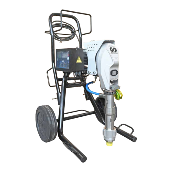
Page 9: Description Of The Equipment
THOR DESCRIPTION OF THE EQUIPMENT Long pumping group Short pumping group Fig. 1 Pos. Description Pos. Description Electric motor Earth cable with clamp Safety valve Recirculation valve Pressure transmitter Pumping group Recirculation tube High pressure flexible pipe of compensation Ø3/8” ED. - Page 10 THOR Fig. 2 Pos. Description Pos. Description Pressure gauge Control equipment Airless manual gun L91X ON/OFF switch Trigger safety clamp Flexible pipe connection Earth cable with clamp ED. 22 - 02/2024 - Cod. 150096...
-
Page 11: Alarm Messages
THOR ALARM MESSAGES When an alarm message has been indicated the machine has to be switched off and on again When the product to be applied is finished the pump “sucks air” using switch (1). and automatically switches to the minimum number of cycles. Each time the machine is switched off, the The alarm messages function is described on the area sign (6). - Page 12 THOR ALARM MESSAGE TABLE Alarm symbol Type of alarm CAuse Solution Maximum current The motor’s current absorption Check the mechanical and hydraulic is too high condition of the equipment. If necessary, take action Dissipator temp. The dissipator temperature is Check that the dissipator surfaces too high are clean and that the dissipator is properly ventilated...
- Page 13 THOR • The supply cable is provided without plug. Before carrying out any checks on the machine Use a plug which guarantees the plant earthing. (maintenance, cleaning, or replacing parts) switch Only a technician or a skilled person should perform the off the machine and wait until it has stopped connection of the plug to the electric cable.
- Page 14 THOR CONNECTION OF THE TOOLING TO THE POWER SUPPLY • Lift the suction unit and immerse it in the bucket that contains the washing liquid. • Connect the clamp to an earthing point. Before connection up the power supply to the equipment, make sure that the electrical system is earthed and complies with regulations.
-
Page 15: Preparing The Product
THOR • Turn the pressure setting knob (6) clockwise to the “CIRCULATION & WASHING” position (drop symbol). Fig. 11 Absolutely avoid to spray solvents indoors. In addition, it is recommended to keep away from the pump in order to avoid the contact between Circulation the solvent fumes and the electric motor. - Page 16 THOR Never use products containing halogen hydrocarbons (as methyle- • Dip the suction pipe (1) into the product tank. ne chloride). If these products come into contact with aluminium parts of the equipment, can provoke dangerous chemical reactions with risk of explosion. REMOVE THE FILTER (9) FOR DENSE PRODUCTS.
- Page 17 THOR • Open the recycling tap (3). Open Fig. 3 • Press the switch (4) “ON” (I) of the equipment. Circulation and washing Fig. 5 • Make sure that the product circulates through the circulation hose (6). • Close the circulation tap (3). Closed Fig.
-
Page 18: Spray Adjustment
THOR SPRAY ADJUSTMENT Safety valve: when working at the maximum pres- sure available, releasing the gun trigger sudden • Slowly turn clockwise the pressure control knob (5) to reach increases of pressure can occur. In this case, the the pressure value in order to ensure a good atomization of safety valve (6) opens automatically eliminating the product. - Page 19 THOR CLEANING AT THE END OF • Hold the spray gun trigger down. THE WORK • Open the circulation tap (3) to discharge the pressure in the circuit. CLEANING FOR SOLVENT-BASED PRODUCTS Make sure that the electrical system is earthed and complies with regulations.
- Page 20 THOR • Turn the pressure setting knob (1) clockwise to the “CIRCU- • Close the circulation tap (J3). LATION & WASHING” position (drop symbol). Closed Fig. 5 • Point the spray gun (4) into the container (5) used to collect the cleaning liquid and hold the trigger down to expel any product remaining, until clean liquid flows out.
- Page 21 THOR • Lift the suction hose and remove the bucket of cleaning • In case of long storage, we recommend you to suck and liquid. to leave light mineral oil inside the pumping group and the flexible hose. • Now point the spray gun (4) into the container (5) and press the trigger to recover any cleaning liquid left.
- Page 22 THOR CLEANING FOR WATER-BASED PRODUCTS • Hold the spray gun trigger down. • Open the circulation tap (3) to discharge the pressure in the Make sure that the electrical system is earthed circuit. and complies with regulations. • Reduce pressure to the minimum (turn counterclockwise the pressure control knob (1)).
- Page 23 THOR Fig. 14 ED. 22 - 02/2024 - Cod. 150096...
-
Page 24: Routine Maintenance
THOR • Run the pump’s washing cycle until clean water flows out of the circulation hose (11). • Close the circulation tap (3). Closed Fig. 15 • Remove the suction hose and the rubber hose (9) and take away the bucket of water (8). Fig. - Page 25 THOR CHECKING THE HEAT EXCHANGE RADIATOR • Use the lubricant (1) provided (ref. 16340) to make it easier to slide the piston inside the seal pack and to substitute the Always keep the heat exchange radiator (4) on the electronic air with oil.
- Page 26 THOR 3- Grease with a grease pump using the nipple (9). REDUCTION BOX GREASING After 100 hours of operation or when you hear a change in the noise on the gearbox, lubricate using the grease nipple, removing the sheet covering the injection nipple. 1- Remove the rear screws (6) and loosen the front screws (7) on the cover (8).
-
Page 27: Problems And Solutions
THOR PROBLEMS AND SOLUTIONS Problem Cause Solution The equipment does not start Lack of voltage; Check the correct connection to the power supply; Considerable drops in mains voltage; Check the extension cable; On/Off switch disconnected; Ensure the On/Off switch is on the “on” position and turn clockwise the pressure control knob;... - Page 28 THOR CORRECT PROCEDURE OF DECOMPRESSION • Open the discharge tap (2) to discharge the residual pressure, Make sure that the electrical system is earthed always turning it anticlockwise. and complies with regulations. • Point the gun at the tank (3) of the product and press the •...
- Page 29 THOR REPLACEMENT OF THE PUMPING GROUP’S GASKETS Each time you use the machine, check for material leaking from the top of the ring nut. Rif. 20213 If any material leaks out when the pump is working at the set pressure, proceed as follows: •...
-
Page 30: Pit Stop Maintenance
THOR Lower seal • Unscrew the pump unit (9) from its housing, as indicated. • Remove the piston stem (10) and remove the pump unit sleeve (11); Countersunk side Fig. 6 PIT STOP MAINTENANCE Replacement of upper and lower gaskets 20 minutes. •... - Page 31 THOR • Use a size 22 spanner to unscrew the lower stem (13); • Unscrew the stem valve (15) altogether, check the surface of the ball seating (16) that comes into contact with the ball (17). If worn, replace them; Fig.
- Page 32 THOR Upper seal • Use a screwdriver to remove the O-Ring (22); • Remove the ring nut (19); Fig. 19 • Use a screwdriver to remove the second O-Ring (23) located under the O-Ring (22) and insert a new O-Ring (23) in the same position;...
- Page 33 THOR Remove the O-Rings (24 and 27) from the foot valve (25) and • the O-Ring (26) and replace if necessary. Refit the components in the correct order (as indicated in the photo); Fig. 24 • Remove the sleeve/cylinder seal (28) and replace it with a new one;...
- Page 34 THOR • Insert the complete piston stem (31) after greasing the gaskets • Grease the sleeve (29) using a paintbrush; (32); Countersunk side of the sleeve Fig. 26 • Insert the sleeve (29) into the lower pump unit (30); The pumping sleeve is countersunk (31) at one end, simply to facilitate connecting with the stem gaskets.
- Page 35 THOR • When refitting the pump unit on the machine, the stem must • Lubricate the upper crown (36) using oil (37) (Ref. 16340); be at its highest point possible. • Insert the stem into the connecting rod and insert the fixing pin (6).
-
Page 37: Spare Parts
THOR SPARE PARTS Electric motor Complete electro-mechanical unit Pressure control device pag. 60 pag. 38 pag. 52 Electrical control pag. 58 Complte repair kit and sleeve/ piston for long pumping unit pag. 42 Spare part kit for short pumping unit pag. - Page 38 THOR COMPLETE ELECTRO-MECHANICAL UNIT ED. 22 - 02/2024 - Cod. 150096...
- Page 39 THOR Pos. Code Description Q.ty 20241 Electric motor 220V 50Hz 37177 Screws 34009 Washer 20250 Bearing 20253 Bearing 20254 Bearing 20257 Bearing 69107 Screw M10x80 20258 Toothed driving assembly 20259 Cam assembly 20262 Complete connecting rod 20263 Positioning spring 20210 Pump unit pivot 20264 Centring pin...
- Page 40 THOR COMPLETE LONG PUMPING UNIT WARNING: Always indicate code and quantity for each part required. Countersank side ED. 22 - 02/2024 - Cod. 150096...
- Page 41 THOR Pos. Code Descripcion Q.ty 20100 Complete long pump unit for heavy products 20101 Suction filter 20130 Assembled valve 19296 Seal 20131 O-ring 95029/1 Ball seat 20149 Closing ball 19273 Ball guide 20132 O-ring 20133 Foot valve assembly for heavy products 20145 Foot valve assembly for standard products 20134...
- Page 42 THOR SPARE KIT FOR LONG PUMPING UNIT Q.1 COMPLETE REPAIR KIT LONG PUMPING UNIT (COD. 40109) SLEEVE KIT PLUS PISTON LONG PUMPING UNIT (COD. 20174) 40109 LONG PUMPING UNIT POMPANTE LUNGO 20174 ED. 22 - 02/2024 - Cod. 150096...
- Page 43 THOR ELECTRO-MECHANICAL UNIT GRUPPO ELETTRO-MECCANICO Kit code Position Description 1, 2x (2), 3, 4, 2x(5), 6, 7, 8, 9, 2x (10), 40109 Complete repair kit for long pumping unit 11, 12, 13, 14, 15, 16, 17, 18, 19 20174 6, 7, 8, 9, 18, 19 Sleeve-kit plus piston long pumping unit ED.
- Page 44 THOR GASKET KIT FOR LONG PUMP UNIT 20173 20167 20168 Kit code Position Description 20173 2x (1), 2, 3, 2x(4), 5, 2x (6), 7, 8, 9, 10, 11 Complete gasket kit for long pumping unit 20167 2x (1), 2 Upper gasket kit for long pumping unit 20168 2x (6), 7, 8 Lower gasket kit for long pumping unit...
- Page 46 THOR SHORT PUMPING UNIT FOR STANDARD PRODUCTS WARNING: Always indicate code and quantity for each part required. CORRECT PROFILE TIGHTENING PIN ASSEMBLY REF. 20144 DRAW. ST 117 SW PAIRED WITH GIOTTO EXTENSION FOR VERSION TYPE SUCTION HOSE WITH PETROL MOTOR REF.
- Page 47 THOR Pos. Code Description Q.ty 20142 Complete short pumping unit 96099 Seal liner 19295 Dip fitting 20172 Union 90° 20130 Assembled valve 20102 Foot valve body 20103 Tightening ring nut 81009 Dowel 19296 Seal 20131 O-ring 20143 Ball housing assembly 19298 Seat for ball housing 95023/1...
- Page 48 THOR SPARE KIT FOR SHORT PUMPING UNIT S.1 COMPLETE REPAIR KIT SHORT PUMPING UNIT (COD. 40109/1) SLEEVE KIT PLUS PISTON SHORT PUMPING UNIT (COD. 20174) SHORT PUMPING UNIT 40109/1 POMPANTE CORTO 20174 ED. 22 - 02/2024 - Cod. 150096...
- Page 49 THOR ELECTRO-MECHANICAL UNIT GRUPPO ELETTRO-MECCANICO Kit code Position Description 1, 2x (2), 3, 4, 5, 6, 7, 2x (8), 9, 10, 40109/1 Complete repair kit for short pumping unit 11, 12, 13, 14, 15, 16, 17, 18 20174 4, 5, 6, 7, 17, 18 Sleeve-kit plus piston short pumping unit ED.
- Page 50 THOR GASKET KIT FOR SHORT PUMPING UNIT 20173/1 20167 20168 Kit code Position Description 20173/1 2x (1), 2, 3, 2x(4), 5, 6, 7, 8, 9, 10 Complete gasket kit for short pumping unit 20167 2x (1), 2 Upper gasket kit for short pumping unit 20168 2x (4), 5, 6 Lower gasket kit for short pumping unit...
- Page 51 THOR FILTER ASSEMBLY: code 37410 WARNING: Always indicate code and quantity for each part required. Pos. Code Description Q.ty Pos. Code Description Q.ty 96205 Dowel Gc 1/4 x 10 96207 Sieve holder 96206 Nipple M-M 1/4” - M16 x 1.5 95218 Filter sieve 96204...
- Page 52 THOR PRESSURE CONTROL DEVICE The Manufacturer declines all responsibility for any damage or malfunction of the machine following tampering or alteration of the valve calibration. ED. 22 - 02/2024 - Cod. 150096...
- Page 53 THOR Pos. Code Description Q.ty 20400 Complete unit 20401 Control stop 20457 Digital pressure switch 20402 Protection 20450 Cable fastener 20436 Screw 20452 3/8 GJ cap with a.p. hexagonal head 20430 Screw 96255 Union AP 20460 Locking connection 20418 Safety discharge pipe 20451 Elbow AP 33035...
- Page 54 THOR SUCTION AND CIRCULATION UNIT FOR STANDARD PRODUCTS WARNING: Always indicate code and quantity for each part required. Pos. Code Description Q.ty Pos. Code Description Q.ty 3373 Reduction Recirculation tube+Safety tube+ 20550 1+1+1 Suction tube 3387 Union 18377 Reduction 18350 Dispersion bell 18378 Swivel connection...
- Page 55 THOR CARRIAGE WARNING: Always indicate code and quantity for each part required. Carriage at maximum height position Carriage in compact position Pos. Code Description Q.ty Pos. Code Description Q.ty 20300 Complete carriage 18902 Split pin 20301 Carrying handle 20305 Wheel stop washer 95159 Pipe cap 20303...
- Page 56 THOR TANK WARNING: Always indicate code and quantity for each part required. ED. 22 - 02/2024 - Cod. 150096...
- Page 57 THOR Pos. Code Description Q.ty 20326 Tank 20329 Cover 20320 Carrying handle 20321 Male plug 20330 Gasket 20322 Female plug 20327 Trolley 8385 Screw 34009 Washer 20303 Wheel 20305 Wheel stop washer 37403 20328 Bag support bar 20325 Bag pressing assembly 20331 Right shoulder 18664...
-
Page 58: Electrical Control
THOR ELECTRICAL CONTROL WARNING: Always indicate code and quantity for each part required. Rif. 20350 220V - 50Hz Pos. Code Description Q.ty Pos. Code Description Q.ty 20350 Complete electronic box 34009 Schorr washer ø 8 5933 Switch 34008 Screw M8x20 UNI 5931 20355 Panel 20340... -
Page 59: Electric Motor
THOR ELECTRIC MOTOR WARNING: Always indicate code and quantity for each part required. DISCONNECT THE POWER SUPPLY BEFORE CHECKING OR REPLACING THE BRUSHES. • Periodically check on the wear of the pinion (at least every 1000 working hours). • Periodically check the perfect connection among all the electrical components (at least every 200 working hours). -
Page 60: Electrical Diagram
THOR ELECTRICAL DIAGRAM BLUE BROWN YELLOW/GREEN YELLOW/GREEN BLUE BROWN Fig. 1 ED. 22 - 02/2024 - Cod. 150096... -
Page 61: Ce Declaration Of Conformity
THOR CE DECLARATION OF CONFORMITY Company LARIUS srl Via Antonio Stoppani 21 - 23801 Calolziocorte (LC) ITALY Tel: +39 0341 621152 Fax: +39 0341 621243 E-mail: larius@larius.com Declares under his owns resonsibility that the product: THOR Electric piston pump complies with the directives: - EC Directive 2006/42 Machinery Directive - EU Directive 2014/30 Electromagnetic Compatibility (EMC) - EU Directive 2014/35 Low Voltage (LVD) - Page 62 TEL. +1 (828) 645-2290 - FAX: +1 (828) 658 0840 TEL.: +44 1942 850600 - FAX: +44 1942 812160 ©Copyright, SAMOA INDUSTRIAL, S.A. SAMOA Industrial, S.A. is an ISO 9001, ISO 14001 and ISO 45001 certified company. Contact us today! Visit www.samoaindustrial.com for more information.
Need help?
Do you have a question about the THOR 20704 and is the answer not in the manual?
Questions and answers