
Related Manuals for Aaeon UP 7000 Edge


Summary of Contents for Aaeon UP 7000 Edge
- Page 1 UP 7000 Edge Maker Board System UP-EDGE-ADLN01 User’s Manual 1st Ed Last Updated: September 18, 2023...
- Page 2 AAEON assumes no liabilities resulting from errors or omissions in this document, or from the use of the information contained herein. AAEON reserves the right to make changes in the product design without notice to its users.
- Page 3 Acknowledgement All other products’ name or trademarks are properties of their respective owners. Microsoft®, Windows®, Windows® 10 LTSC 2021 are registered trademarks of ⚫ Microsoft Corp. Intel® is a registered trademark of Intel Corporation ⚫ Yocto Project® is a trademark of The Linux Foundation. ⚫...
- Page 4 Packing List Before setting up your product, please make sure the following items have been shipped: Item Quantity UP-EDGE-ADLN01 (UP 7000 Edge) ⚫ If any of these items are missing or damaged, please contact your distributor or sales representative immediately. Preface...
- Page 5 (if any), its specifications, dimensions, jumper/connector settings/definitions, and driver installation instructions (if any), to facilitate users in setting up their product. Users may refer to the product page at AAEON.com for the latest version of this document. Preface...
- Page 6 Safety Precautions Please read the following safety instructions carefully. It is advised that you keep this manual for future references All cautions and warnings on the device should be noted. Make sure the power source matches the power rating of the device. Position the power cord so that people cannot step on it.
- Page 7 If any of the following situations arises, please the contact our service personnel: Damaged power cord or plug Liquid intrusion to the device iii. Exposure to moisture Device is not working as expected or in a manner as described in this manual The device is dropped or damaged Any obvious signs of damage displayed on the device...
- Page 8 FCC Statement This device complies with Part 15 FCC Rules. Operation is subject to the following two conditions: (1) this device may not cause harmful interference, and (2) this device must accept any interference received including interference that may cause undesired operation.
- Page 9 China RoHS Requirements (CN) 产品中有毒有害物质或元素名称及含量 AAEON System QO4-381 Rev.A0 部件名称 有毒有害物质或元素 铅 汞 镉 六价铬 多溴联苯 多溴二苯醚 (Pb) (Hg) (Cd) (Cr(VI)) (PBB) (PBDE) 印刷电路板 × ○ ○ ○ ○ ○ 及其电子组件 外部信号 × ○ ○ ○ ○ ○ 连接器及线材 ○...
- Page 10 China RoHS Requirement (EN) Hazardous and Toxic Materials List AAEON System QO4-381 Rev.A0 Hazardous or Toxic Materials or Elements Component Name PCB and Components Wires & Connectors for Ext.Connections Chassis CPU & RAM HDD Drive LCD Module Optical Drive Touch Control...
-
Page 11: Table Of Contents
Table of Contents Chapter 1 - Product Specifications..................1 Specifications ......................2 Chapter 2 – Hardware Information ..................4 Dimensions ....................... 5 Jumpers and Connectors ..................6 List of Jumpers and Connectors ................8 2.3.1 Power Button (SW1) ..................9 2.3.2 LAN Port (CN2) .................... -
Page 12: Chapter 1 - Product Specifications
Chapter 1 Chapter 1 - Product Specifications... -
Page 13: Specifications
Specifications System Intel® Processor N200 Intel® Processor N97 Intel® Processor N100 Intel® Processor N50 (formerly Alder Lake-N) Memory Up to 8GB LPDDR5 Graphics Intel® UHD Graphics for 12th Gen Intel® Processors Storage Up to 64GB eMMC Ethernet 1GbE RJ-45 x 1 (Realtek RTL8111H CG) Wi-Fi/BT —... - Page 14 Power Supply Power Requirement 12V DC-in, 5A Power Supply Type AT (default)/ATX Power Consumption (Typical) 30W~36W Mechanical Mounting VESA Mount (optional) Dimensions (WxHxD) 3.62” x 2.52” x 1.78” (92mm x 64mm x 45.2mm) Net Weight 0.68 lb. (0.31Kg) Gross Weight 1.04 lb.
-
Page 15: Chapter 2 - Hardware Information
Chapter 2 – Hardware Information Chapter 2... -
Page 16: Dimensions
Dimensions Chapter 2 – Hardware Information... -
Page 17: Jumpers And Connectors
Jumpers and Connectors Top: Chapter 2 – Hardware Information... - Page 18 Bottom: Chapter 2 – Hardware Information...
-
Page 19: List Of Jumpers And Connectors
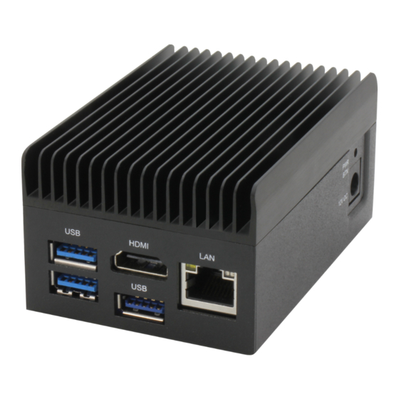
List of Jumpers and Connectors Please refer to the table below for all of the board’s jumpers and connectors that you can configure for your application Label Function Power Button LAN Port HDMI/USB (Type-A) Dual USB Port (Type-A) DC Power Jack Note: Not all PCBA-level internal connector pins are accessible via edge system external ports. -
Page 20: Power Button (Sw1)
2.3.1 Power Button (SW1) Signal Signal PWR_SW# 2.3.2 LAN Port (CN2) Signal Signal LAN1_MDI0+ LAN1_MDI0- LAN1_MDI1+ LAN1_MDI1- CT_GND CT_GND LAN1_MDI2+ LAN1_MDI2- Chapter 2 – Hardware Information... -
Page 21: Hdmi/Usb (Type-A) (Cn5)
Signal Signal LAN1_MDI3+ LAN1_MDI3- LAN Link LED 1000# LAN Link LED 100# LAN Active LED_N LAN Active LED_P Chassis GND Chassis GND 2.3.3 HDMI/USB (Type-A) (CN5) Signal Signal HDMI_TMDS_TXP2 HDMI_TMDS_TXN2 HDMI_TMDS_TXP1 HDMI_TMDS_TXN1 HDMI_TMDS_TXP0 HDMI_TMDS_TXN0 HDMI_TMDS_Clock_P HDMI_TMDS_Clock_N HDMI_DDC_Clock HDMI_DDC_Data 5V@1A for HDMI HDMI Hot Plug detect pin 5V@0.9A for USB 3.2 USB2.0_DN3... -
Page 22: Dual Usb Port (Type-A) (Cn6)
Signal Signal USB2.0_DP3 USB3.2_RXN3 USB3.2_RXP3 USB3.2_TXN3 USB3.2_TXP3 2.3.4 Dual USB Port (Type-A) (CN6) Signal Signal 5V@0.9A for USB 3.2 USB2.0_DN1 USB2.0_DP1 USB3.2_RXN1 USB3.2_RXP1 USB3.2_TXN1 USB3.2_TXP1 5V@0.9A for USB 3.2 USB2.0_DN2 USB2.0_DP2 USB3.2_RXN2 USB3.2_RXP2 USB3.2_TXN2 USB3.2_TXP2 Chapter 2 – Hardware Information... -
Page 23: Dc Power Jack (Cn8)
2.3.5 DC Power Jack (CN8) Signal Signal Chapter 2 – Hardware Information... -
Page 24: Chapter 3 - Software Installation
Chapter 3 Chapter 3 – Software Installation... -
Page 25: Linux Setup
The UP 7000 Edge supports Linux operating systems (see Chapter 1 for specifications). For instructions on how to install a Linux OS onto your UP 7000 Edge, you can find several guides and tutorials in the wiki section of the UP Board website at https://up-board.org... -
Page 26: Appendix A - Up Framework Sdk Installation
Appendix A Appendix A – UP Framework SDK Installation... -
Page 27: Introduction
Introduction This section provides instructions for the installation of the UP Framework SDK. Instructions are provided for Windows 10 and Windows IoT Core. You can download the latest version of UP Framework SDK from the UP community: https://downloads.up-community.org/download/up-sdk-for-windows-10-and-window s-iot/ A.2 Installation for Windows 10 Step 1 Locate the downloaded file UpFrameworkSetup.msi and run the installer. - Page 28 Step 2 Select the installation folder. Default destination path is C:\Program Files(x86)\AAEON\ You may also choose to install the UP Framework SDK for all users or only the current user. Press “Next” to continue installation. Step 3 Press “Next” to confirm the installation.
- Page 29 Step 4 Press “Close” to exit once setup is complete. Appendix A – UP Framework SDK Installation...
Need help?
Do you have a question about the UP 7000 Edge and is the answer not in the manual?
Questions and answers