
Related Manuals for Aaeon UP Squared 6000 Edge


Summary of Contents for Aaeon UP Squared 6000 Edge
- Page 1 UP Squared 6000 Edge Computing Kit Edge System UPN-EDGE-EHL01-FDK User’s Manual 2 Last Updated: September 26, 2022...
- Page 2 AAEON assumes no liabilities resulting from errors or omissions in this document, or from the use of the information contained herein. AAEON reserves the right to make changes in the product design without notice to its users.
- Page 3 Acknowledgement All other products’ name or trademarks are properties of their respective owners. Microsoft®, Windows® are registered trademarks of Microsoft Corp. ⚫ Intel®, Pentium®, and Celeron® are registered trademarks of Intel Corporation ⚫ Intel Atom™ is a trademark of Intel Corporation ⚫...
- Page 4 Packing List Before setting up your product, please make sure the following items have been shipped: Item Quantity UPN-EDGE-EHL01-FDK with heatsink ⚫ (UP Squared 6000 Edge Computing Kit) Quick Start Guide ⚫ 40Pin Phoenix Connector ⚫ 12V/6A Power Adapter ⚫...
- Page 5 (if any), its specifications, dimensions, jumper/connector settings/definitions, and driver installation instructions (if any), to facilitate users in setting up their product. Users may refer to the product page at AAEON.com for the latest version of this document. Preface...
- Page 6 Safety Precautions Please read the following safety instructions carefully. It is advised that you keep this manual for future references All cautions and warnings on the device should be noted. Make sure the power source matches the power rating of the device. Position the power cord so that people cannot step on it.
- Page 7 If any of the following situations arises, please the contact our service personnel: Damaged power cord or plug Liquid intrusion to the device iii. Exposure to moisture Device is not working as expected or in a manner as described in this manual The device is dropped or damaged Any obvious signs of damage displayed on the device...
- Page 8 FCC Statement This device complies with Part 15 FCC Rules. Operation is subject to the following two conditions: (1) this device may not cause harmful interference, and (2) this device must accept any interference received including interference that may cause undesired operation.
- Page 9 China RoHS Requirements (CN) 产品中有毒有害物质或元素名称及含量 AAEON System QO4-381 Rev.A0 有毒有害物质或元素 部件名称 铅 汞 镉 六价铬 多溴联苯 多溴二苯醚 (Pb) (Hg) (Cd) (Cr(VI)) (PBB) (PBDE) 印刷电路板 × ○ ○ ○ ○ ○ 及其电子组件 外部信号 × ○ ○ ○ ○ ○ 连接器及线材 ○...
- Page 10 China RoHS Requirement (EN) Hazardous and Toxic Materials List AAEON System QO4-381 Rev.A0 Hazardous or Toxic Materials or Elements Component Name PCB and Components Wires & Connectors for Ext.Connections Chassis CPU & RAM HDD Drive LCD Module Optical Drive Touch Control...
-
Page 11: Table Of Contents
Table of Contents Chapter 1 - Product Specifications..................1 Specifications ......................2 Chapter 2 – Hardware Information ..................4 Dimensions ....................... 5 Mainboard Jumpers and Connectors ..............6 Mainboard List of Jumpers and Connectors............8 2.3.1 PWR Button (SW1) ..................9 2.3.2 RTC (CN28) .................... - Page 12 2.3.21 AUDIO (CN66) .................... 25 2.3.22 FAN (J1) ......................26 2.3.23 AT/ATX mode (JP7) ..................26 Mainboard Connector Index ................27 Carrier board Jumpers and Connectors ............29 Carrier board Connector Index ................31 2.6.1 Mini card (CN2) ..................32 2.6.2 SATA (CN3) ....................
-
Page 13: Chapter 1 - Product Specifications
Chapter 1 Chapter 1 - Product Specifications... -
Page 14: Specifications
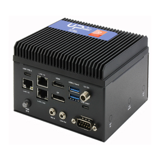
Specifications System Intel® Atom® X6425RE Processor SoC Memory Onboard 8GB DDR4 Graphics Intel® UHD Graphics Storage Onboard eMMC 64G Ethernet GbE x 3 (Intel® i210-IT x 1, Marvell Alaska x 2 from PSE), 2.5GbE x 1 (i225-IT) WIFI/BT Optional with M.2 2230 E-Key x 1 Audio Line out x 1 Mic in x 1... - Page 15 I/O Placements Power DC-in Jack x 1, Power Button x 1 USB 3.2 Gen 2 Type A x 2 USB 3.2 Gen 2 Type C (support OTG) x 1 Micro USB (PSE debug port) x 1 Display Port HDMI 2.0b x 1 DP 1.2 x 1 Ethernet RJ45 x 4...
-
Page 16: Chapter 2 - Hardware Information
Chapter 2 – Hardware Information Chapter 2... -
Page 17: Dimensions
Dimensions System Chapter 2 – Hardware Information... -
Page 18: Mainboard Jumpers And Connectors
Mainboard Jumpers and Connectors Top: Chapter 2 – Hardware Information... - Page 19 Bottom: Chapter 2 – Hardware Information...
-
Page 20: Mainboard List Of Jumpers And Connectors
Mainboard List of Jumpers and Connectors Please refer to the table below for all of the board’s jumpers that you can configure for your application Label Function PWR button CN28 CN35 M.2 Key-B Slot CN36 M.2 Key-E Slot CN38 USB Type A DUAL PORT CN39 SATA CONN CN40... -
Page 21: Pwr Button (Sw1)
2.3.1 PWR Button (SW1) Switch Position Function SW1 1 (default) SW1 0 Power ON 2.3.2 RTC (CN28) Signal RTC_VCC Chapter 2 – Hardware Information... -
Page 22: Key-B Slot (Cn35)
2.3.3 M.2 Key-B Slot (CN35) Signal Signal Signal +3.3V +3.3V FULL_CARD_POWER_OFF# USB2_D+ W_DISABLE#1 USB2_D- USB3_RX- UIM_RST USB3_RX+ UIM_CLK UIM_DAT USB3_PX- UIM_PWR USB3_PX+ PCIE10_RXN PCIE_RXP PCIE_TXN PCIE10_TXP PLT_RST#(3.3V) PCIE_CLKREQ# PCIE_CLKN PCIE_WAKE# PCIE_CLKP Chapter 2 – Hardware Information... -
Page 23: Key-E Slot (Cn36)
Signal Signal Signal PLT_RST#(1.8V) +3.3V +3.3V +3.3V 2.3.4 M.2 Key-E Slot (CN36) Signal Signal Signal +3.3V USB2_D+ +3.3V USB2_D- CNV_BRI_RSP CNV_RGI_DT CNV_RGI_RSP PCIE_TXP CNV_BRI_DT Chapter 2 – Hardware Information... - Page 24 Signal Signal Signal PCIE_TXN PCIE_RXP PCIE_RXN PCIE_CLKP PCIE_CLKN SUS_CLK WIFI_RST# PCIE_CLKREQ# BT_EN PCIE_WAKE# WIFI_EN +3.3V +3.3V Chapter 2 – Hardware Information...
-
Page 25: Usb Type A Dual Port (Cn38)
2.3.5 USB Type A DUAL PORT (CN38) Signal Signal Signal USB2_D1- USB2_D1+ USB3_RX1- USB3_RX1+ USB3_TX1- USB3_TX1+ USB2_D2- USB2_D2+ USB3_RX2- USB3_RX2+ USB3_TX2- USB3_TX2+ 2.3.6 SATA CONN (CN39) Signal Signal SATA_TXP0 SATA_TXN0 SATA_RXN0 SATA_RXP0 Chapter 2 – Hardware Information... -
Page 26: Sata Power (Cn40)
2.3.7 SATA POWER (CN40) Signal Signal +V5S 2.3.8 LAN DUAL PORT (CN41) Signal Signal Signal LAN1_MDI0+ LAN1_MDI0- LAN1_MDI1+ LAN1_MDI1- LAN1_MDI2+ LAN1_MDI2- LAN1_MDI3+ LAN1_MDI3- R10A LAN1_ACTLED- LAN1_ACTLED+ LAN1_LINK1000# LAN1_LINK100# LAN2_MDI0+ LAN2_MDI0- LAN2_MDI1+ LAN2_MDI1- LAN2_MDI2+ LAN2_MDI2- LAN2_MDI3+ LAN2_MDI3- R10B LAN2_ACTLED- LAN2_ACTLED+ LAN2_LINK1000# LAN2_LINK100# Chapter 2 –... -
Page 27: Hdmi/ Dp (Cn43)
2.3.9 HDMI/ DP (CN43) Signal Signal Signal DP_TXP0 DP_TXN0 DP_TXP1 DP_TXN1 DP_TXP2 DP_TXN2 DP_CLK+ DP_CLK- CONFIG1 CONFIG2 DP_AUX_P DP_AUX_N DP_HPD 3.3V HDMI_TXP0 HDMI_TXN0 HDMI_TXP1 HDMI_TXN1 HDMI_TXP2 HDMI_TXN2 HDMI_CLK+ HDMI_CLK- HDMI_CEC DDC_CLK DDC_DATA HDMI_HPD Chapter 2 – Hardware Information... -
Page 28: Hat40 (Cn44)
2.3.10 HAT40 (CN44) Signal Signal +3.3V GP_H06/SIO_I2C3_SDA GP_H07/SIO_I2C3_SCL GP_F07/PSE_I2S1_SCLK GP_C13_USUART0_TX GP_C12_HSUART0_RX GP_C14_HSUART0_RS232_RTS_RS48 HAT_I2S2_CLK 5_DE GP_H19_TGPIO0 GP_E23/PSE_PWM15/PSE_TGPI GP_B14_TGPIO1 GP_E22/PSE_PWM14/PSE_TGPI +3.3V GP_B22/SIO_SPI1_MOSI GP_B21/SIO_SPI1_MISO GP_B11_PSE_TGPIO06 GP_B20/SIO_SPI1_CLK GP_B19/SIO_SPI1_CS0_N GP_B23/SIO_SPI1_CS1_N GP_B09_I2C5_SDA GP_B10_I2C5_SCL GP_F18/PSE_I2S1_TXD GP_F19/PSE_I2S1_RXD GP_C05 GP_D04/PSE_PWM02 HAT_I2S2_FRM GP_C15_HSUART0_RS232_CTS GP_F10/PSE_I2S1_SFRM HAT_I2S2_RX HAT_I2S2_TX Chapter 2 – Hardware Information... -
Page 29: Key-M Slot (Cn48)
2.3.11 M.2 Key-M Slot (CN48) Signal Signal Signal +3.3V +3.3V +3.3V +3.3V +3.3V +3.3V SSD_DEV_SLP SMB_CLK_1V8 PCIE_RXN SMB_DATA_1V8 PCIE_RXP PCIE_TXN PCIE_TXP PLT_RST# PCIE_CLKREQ# PCIE_CLKN PCIE_WAKE# PCIE_CLKP Chapter 2 – Hardware Information... -
Page 30: Usb2.0/ Uart 1X10P Wafer (Cn49)
Signal Signal Signal +3.3V +3.3V +3.3V 2.3.12 USB2.0/ UART 1x10P Wafer (CN49) Signal Signal Signal USB2_D5- USB2_D5+ USB2_D6- USB2_D6+ UART_RX UART_TX 2.3.13 DC Jack (CN50) Signal Signal Signal DC_IN Chapter 2 – Hardware Information... -
Page 31: Edp (Cn55)
2.3.14 eDP (CN55) Signal Signal +VDD_3V3 +VDD_3V3 EDP_TXN2 EDP_TXP2 EDP_TXN1 EDP_TXP1 EDP_TXN0 EDP_TXP0 EDP_TXN3 EDP_TXP3 EDP_AUXN EDP_AUXP BKLT_CTRL BKLT_EN EDP_HPD +12V +12V +12V +12V Chapter 2 – Hardware Information... -
Page 32: Bios Update (Cn57)
2.3.15 BIOS UPDATE (CN57) Signal Signal SPI_MISO SPI_CLK +VCC_SPI SPI_MOSI SPI_CS0# 2.3.16 DOCKING (CN58) Signal Signal Signal VCC_12V VCC_12V VCC_12V VCC_12V VCC_12V USB2_P9_DP VCC_12V USB2_P9_DN GP_E15/PSE_CA N0_TX GP_H07/SIO_I2C GP_E16/PSE_CA GP_H06/SIO_I2C 3_SCL N0_RX 3_SDA GP_E20/CAN1_T Chapter 2 – Hardware Information... - Page 33 Signal Signal Signal GP_D00/PSE_QE GP_E21/CAN1_R GP_D13/PSE_QE GP_T00/PSE_QE GP_D15/PSE_PW GP_U07/PSE_QE GP_D17/PSE_PW GP_D01/PSE_QE GP_D18/PSE_PW GP_D14/PSE_QE GP_D03/PSE_P WM06 GP_T01/PSE_QE GP_U11/PSE_QE GP_D02/PSE_QE SIO_SPI_1_CLK SIO_SPI_1_TXD GP_D16/PSE_QE GP_T02/PSE_QE SIO_SPI_1_RXD GP_U19/PSE_QE SIO_SPI_1_FS1 GP_H21_HSUAR GP_H13_USUART T1_RS232_RTS_R 1_TX S485_DE GP_H15_HSUAR ENET_A_RST ENET_A_INT T1_RS232_CTS GP_H12_HSUAR RGMII_A_SMA_ GP_H22_HSUAR T1_RX T1_RS485_RE_N GP_H23_HSUAR RGMII_A_SMA_ GBE0_RGMII_R_T T1_RS485_RS232...
-
Page 34: Usb3.1 Connector (Cn61)
Signal Signal Signal GBE0_RGMII_RX GBE0_RGMII_RX GP_T07_PSE_GB GBE1_RGMII_RX GBE1_RGMII_RX E0_PPS_PSE_TGP IO59 GP_T06_PSE_GB GBE1_RGMII_RX GP_H03_PSE_GB E0_AUXTS_USB2 _OC1_N GBE1_RGMII_RX GBE1_RGMII_RX GP_H02 GBE1_RGMII_RX PCIE_P9_SATA_P 1_TXP PCIE_P9_SATA_P SLP_S3# 1_TXN PCIE_P9_SATA_P BUF_PLT_RST# 1_RXP PCIE_P9_SATA_P BUF_PLT_RST# 1_RXN 2.3.17 USB3.1 CONNECTOR (CN61) Signal Signal TX_P1_P TX_P2_P TX_P1_N TX_P2_N USB_VBUS USB_VBUS TYPEC_CC1... -
Page 35: Rs232/ 422 (Cn62)
Signal Signal USB2_P1_DP USB2_P2_DP USB2_P1_DN USB2_P2_DN USB_VBUS USB_VBUS RX_ P1 _N RX_P2_N RX_ P1_ P RX_P2_P 2.3.18 RS232/ 422 (CN62) Signal Signal CTS/RX- RTS/TX+ TX/TX- RX/RX+ Chapter 2 – Hardware Information... -
Page 36: Swd (Cn64)
Cable Signal Signal RX/RS422TX- TX/RS422TX+ RTS/RS422RX+ CTS/RS422RX- 2.3.19 SWD (CN64) Signal Signal DBRESET PSE_SWDIO PSE_SWCLK PSE_TRACESWO PSE_TRACECLK PSE_TRACEDATA_0 PSE_TRACEDATA_1 PSE_TRACEDATA_2 PSE_TRACEDATA_3 Chapter 2 – Hardware Information... -
Page 37: Front Panel (Cn65)
2.3.20 Front Panel (CN65) Signal Signal RESET POWER S/W 2.3.21 AUDIO (CN66) Signal Signal LOUT_R LOUT_L +V5S_AUD AUDIO-JD MIC_IN_JD Chapter 2 – Hardware Information... -
Page 38: Fan (J1)
2.3.22 FAN (J1) Signal Signal FAN_TAC FAN_CTL 2.3.23 AT/ATX mode (JP7) Signal Signal ATX_MODE PWRBTN AT_MODE Chapter 2 – Hardware Information... -
Page 39: Mainboard Connector Index
Mainboard Connector Index Label Function Connector Type (TF)Push Button button Switch.3P .12VDC.50mA.500mohm.Black.SMD.HCH.PTS-099 CN28 (TF)WAFER BOX.2P .180D(M).DIP .1.25mm.PINREX.712-71-02TW01 (TF)M 2 Key-B Slot.75P .90D(F).SMD.H=8.5mm CN35 Key-B conn.FOXCONN.AS0BC21-S85BB-7H Slot (TF)M.2 Key-E Slot.75P .90D(F).SMD.Pitch CN36 Key-E 0.5mm.H=6.7mm.BLACK.FOXCONN.AS0BC21-S67BE-LH Slot USB Type (TF)USB3.0 CONNECTOR.DUAL CN38 DUAL PORT.18P .90D(F).DIP .LOTES.ABA-USB-254-K01 PORT SATA... - Page 40 Label Function Connector Type (TF)BOARD-BOARD CONN..SMD.100P .180D.FEMALE.Pitch=0.5mm.H=18.18mm.Floating CN58 Docking Connector for High-Speed Transmission.KEL CORPORATION.DT11-100S-20-T (TF)USB Type C CN61 TYPE C Connector.24P .90D(F).W/30u-Au.SMD.AMCO.211-202451-085 RS232 / CN62 (TF)Wafer Box.6P .180D.(M).SMD.1.0mm.w/ CAP .CATCH.1204-700-06SMR 1x6P Wafer (TF)TERMINAL.2P*1.90D(M).DIP .Pitch=5.0mm.BLOCK.w/ L(+)&R(-) CN63 terminal MARK.DINKLE.DT-126VP-S2016002P block CN64 (TF)Wafer Box.10P .90D(M).SMD.1.0mm.PINREX.710-74-10TWR6 Front Panel...
-
Page 41: Carrier Board Jumpers And Connectors
Carrier board Jumpers and Connectors Chapter 2 – Hardware Information... - Page 42 Bottom Chapter 2 – Hardware Information...
-
Page 43: Carrier Board Connector Index
Carrier board Connector Index Label Functional Description Mini card SATA SATA POWER USB WAFER PSE DEBUG PORT LAN1 CN10 LAN2 CN11 HAT 40 CN12 DOCKING CN13 COM PORT CN15 Chapter 2 – Hardware Information... -
Page 44: Mini Card (Cn2)
2.6.1 Mini card (CN2) Signal Description Signal Description VCC3_MINIPCIE V1.5S P_UIM_PWR P_UIM_DAT P_UIM_CLK P_UIM_RST P_UIM_VPP WL_DISABLE0# 3G_RST VCC3_MINIPCIE V1.5S USB2_DN_R USB2_DP_R VCC3_MINIPCIE VCC3_MINIPCIE Chapter 2 – Hardware Information... -
Page 45: Sata (Cn3)
Signal Description Signal Description V1.5S VCC3_MINIPCIE 2.6.2 SATA (CN3) Signal Description Signal Description SATA_TXP0_C SATA_TXN0_C SATA_RXN0_C SATA_RXP0_C 2.6.3 SATA POWER (CN4) Signal Description Signal Description +V5S Chapter 2 – Hardware Information... -
Page 46: Usb Wafer (Cn6)
2.6.4 USB WAFER (CN6) Signal Description Signal Description Signal Description UART_RX UART_TX 2.6.5 PSE DEBUG PORT (CN7) Signal Description Signal Description USB+ USB- Chapter 2 – Hardware Information... -
Page 47: Lan1/Lan2 (Cn9/10)
2.6.6 LAN1/LAN2 (CN9/10) Signal Description LAN1_TMDI0+ LAN1_TMDI0- LAN1_TMDI1+ LAN1_TMDI2+ LAN1_TMDI2- LAN1_TMDI1- LAN1_TMDI3+ LAN1_TMDI3- Chapter 2 – Hardware Information... -
Page 48: Hat (Cn11)
2.6.7 HAT (CN11) Signal Description Signal Description +3.3V +3.3V CAN0_L CAN0_H CAN1_L CAN1_H GP_D00/PSE_QEPA0 GP_D01/PSE_QEPB0 GP_D13/PSE_QEPA1 GP_D14/PSE_QEPB1 GP_T00/PSE_QEPA2 GP_T01/PSE_QEPB2 GP_U07/PSE_QEPA3 GP_U11/PSE_QEPB3 GP_D02/PSE_QEPI0 GP_T02/PSE_QEPI2 GP_D16/PSE_QEPI1 GP_U19/PSE_QEPI3 GP_D18/PSE_PWM05 GP_D15/PSE_PWM03 GP_D03/PSE_PWM06 GP_D17/PSE_PWM04 ADC_GND ADC_GND ADC0 ADC2 ADC1 ADC3 ADC_GND ADC_GND GP_H04_SIO_I2C2_SDA GP_H05_SIO_I2C2_SCL Chapter 2 – Hardware Information... -
Page 49: Docking (Cn12)
2.6.8 DOCKING (CN12) Signal Description Signal Description Signal Description VCC_12V VCC_12V VCC_12V VCC_12V VCC_12V USB2_P9_DP VCC_12V USB2_P9_DN GP_E15/PSE_CAN0 GP_H07/SIO_I2C3_ GP_E16/PSE_CAN0 GP_H06/SIO_I2C3_ GP_E20/CAN1_TX GP_D00/PSE_QEP GP_D13/PSE_QEPA GP_E21/CAN1_RX GP_T00/PSE_QEPA GP_D15/PSE_PWM GP_U07/PSE_QEPA GP_D17/PSE_PWM GP_D01/PSE_QEPB Chapter 2 – Hardware Information... - Page 50 Signal Description Signal Description Signal Description GP_D18/PSE_PWM GP_D14/PSE_QEPB GP_D03/PSE_PW GP_T01/PSE_QEPB GP_U11/PSE_QEPB GP_D02/PSE_QEPI SIO_SPI_1_CLK SIO_SPI_1_TXD GP_T02/PSE_QEPI GP_D16/PSE_QEPI1 SIO_SPI_1_RXD GP_U19/PSE_QEPI SIO_SPI_1_FS1 GP_H21_HSUART1_ GP_H13_USUART1_ RS232_RTS_RS485 GP_H15_HSUART1_ ENET_A_RST ENET_A_INT RS232_CTS GP_H12_HSUART1_ RGMII_A_SMA_MD GP_H22_HSUART1 _RS485_RE_N RGMII_A_SMA_MD GP_H23_HSUART1 GBE0_RGMII_R_TX _RS485_RS232_N GBE0_RGMII_R_TX ENET_B_RST GBE0_RGMII_R_TX GBE0_RGMII_R_TX ENET_B_INT RGMII_B_SMA_MD GBE0_RGMII_R_TX RGMII_B_SMA_MD Chapter 2 –...
- Page 51 Signal Description Signal Description Signal Description GBE0_RGMII_R_TX GBE1_RGMII_R_TX GBE1_RGMII_R_TX GBE0_RGMII_RXCL GBE1_RGMII_R_TX GBE0_RGMII_RXCT GBE1_RGMII_R_TX GBE0_RGMII_RXD0 GBE1_RGMII_R_TX GBE1_RGMII_R_TX GBE0_RGMII_RXD1 GBE0_RGMII_RXD2 GBE0_RGMII_RXD3 GP_T07_PSE_GBE0 GBE1_RGMII_RXCL GBE1_RGMII_RXCT _PPS_PSE_TGPIO5 GP_T06_PSE_GBE0 _AUXTS_USB2_OC GBE1_RGMII_RXD0 GP_H03_PSE_GBE1 GBE1_RGMII_RXD1 GP_H02 GBE1_RGMII_RXD2 PCIE_P9_SATA_P1_ GBE1_RGMII_RXD3 PCIE_P9_SATA_P1_ SLP_S3# PCIE_P9_SATA_P1_ BUF_PLT_RST# PCIE_P9_SATA_P1_ BUF_PLT_RST# Chapter 2 – Hardware Information...
-
Page 52: Com Port (Cn13)
2.6.9 COM PORT (CN13) Signal Description Signal Description CTS/RX- RTS/TX+ TX/TX- RX/RX+ Cable Signal Signal RX/RS422TX- TX/RS422TX+ RTS/RS422RX+ CTS/RS422RX- Chapter 2 – Hardware Information... -
Page 53: Swd (Cn15)
2.6.10 SWD (CN15) Signal Description Signal Description DBRESET PSE_SWDIO PSE_SWCLK PSE_TRACESWO PSE_TRACECLK PSE_TRACEDATA_0 PSE_TRACEDATA_1 PSE_TRACEDATA_2 PSE_TRACEDATA_3 Chapter 2 – Hardware Information... -
Page 54: Carrier Board List Of Jumpers And Connectors
Carrier Board List of Jumpers and Connectors Reference Functional Connector Type Designation Description (TF)MINIPCI Mini card SLOT.52P .H=5.6mm.SMD.FOXCONN.AS0B22x-S56Q-7 (TF)SATA SATA CONNECTOR.7P .180D(M).SMT.TechBest.007-01-00757 (TF)WAFER SATA POWER BOX.2P .180D(M).DIP .2.0mm.w/LOCK.PINREX.721-81-02 TW00 (TF)Wafer USB WAFER Box.10P .90D(M).SMD.1.0mm.PINREX.710-74-10TWR6 (TF)Micro USB PSE DEBUG Conn..5P .90D(F).SMD.AB-type.TRONTEK.TMC106-USB PORT D05-835 (TF)RJ45.14P .90D(F)W/TF(10/100/1000Base).&... -
Page 55: Chapter 3 - Software Installation
Chapter 3 Chapter 3 – Software Installation... -
Page 56: Pre-Installed Os And Sw Tool Kit
Pre-installed OS and SW tool kit Ubuntu 20.04 LTS and 5.13 Kernel ⚫ Intel® Distribution of OpenVINO™ toolkit 2021 ⚫ Intel® Media SDK ⚫ Intel® Distribution for Python* ⚫ MRAA and UPM I/O and sensor libraries for C++, Python*, Java*, and JavaScript* ⚫... -
Page 57: Bios Setup
BIOS Setup To start using Intel PSE, please follow below step to adjust BIOS default: Chipset-> PSE Configuration-> PSE Controller [Disabled]-> [Enabled] For instructions of BIOS setup guide for PSE, you can find related updates in the wiki section of the UP Board website at https://up board.org. Chapter 3 –... -
Page 58: Appendix A - Cables And Connectors
Appendix A Appendix A – Cables and Connectors... -
Page 59: Cables And Connectors
Cables and Connectors This table provides detailed information about the cables and connectors used by the UP Squared 6000 Edge Computing Kit (UPN-EDGE-EHL01-FDK). If you have any questions about the configuration of your board, please contact your AAEON sales representative.
Need help?
Do you have a question about the UP Squared 6000 Edge and is the answer not in the manual?
Questions and answers