Advertisement
TECHNICAL DATA
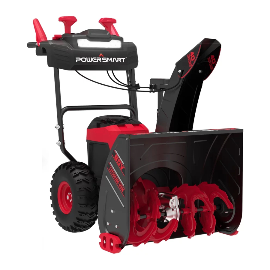
| 24-inch Two Stage Cordless Snow Blower | |
| Model #: | DB2805RB |
| Battery Voltage: | 80V |
| Battery Capacity: | 6Ah |
| Charging Time: | 90mins |
| Clearing Width: | 24 inch |
| Clearing Height: | 20 inch |
| Battery model: | DB2108 |
| Charger model: | DB2208 |
| Chute Rotation Angle: | 180º |
| Wheel Size: | 13 inch |
| Overall Dimensions | 31.3x24.6x23.43 inch |
| Weight: | 140.8 lbs |
It is crucial and highly recommended that you read this instruction manual in its' entirety, as this is an invaluable tool and reference point in understanding the operation of yourunit.
Please register your unit online at www.Amerisuninc.com. This process will allow us to track your warranty information and update our records regarding your unit accordingly.

Our company does not provide email or personal information to any third party for any reason. For any questions check our website or call customer service at (800)791 9458.
INTRODUCTION
This manual provides information regarding the safe operation and maintenance of this product. Every effort has been made to ensure the accuracy of the information in this manual. PowerSmart® reserves the right to change this product and specifications at any time without prior notice.
Please keep this manual available to all users during the entire life of the snow Blower.
 This manual contains special messages to bring attention to potential safety concerns, snow blower damage as well as helpful operating and servicing information. Please read all the information carefully to avoid injury and machine damage.
QUESTIONS? PROBLEMS?
Please contact our Customer Service Dept. with any questions and/or comments, either by email: support@amerisuninc.com, or Toll Free at (800) 791-9458. We are available Mon-Fri 9am-5pm EST to help solve any issues that you might encounter.
KNOWING YOUR SNOW BLOWER
Please use the illustration below to familiarize yourself with the location and function of the components that control of your snow blower.

- Left auger welding
- Impeller welding
- Right auger welding
- Housing
- Skid shoes
- Chassis welding
- Auger control
- Drive control
- Forward and reverse control switch
- Chute deflector control
- Chute Steering control
- Control board
- LED Light
- Clean Out Tool
- Upper Handle
- Lower Handle
- Battery Box
- Chute
- Chute deflector
- Drive control
- LED Light Button
- Charger
- Battery pack
ON/OFF
Located in the middle of the panel, the ON/FF button must be pressed down before motor can be started.
Auger Control Trigger
Located on the left side of the handle, the Auger Control Trigger is used to engage and disengage the augers. Squeeze the Auger Control Trigger to engage the augers; release to disengage the augers.
Drive Control Trigger
Located on the right side of the handle, the Drive Control Trigger is used to engage and disengage the drive wheels. Squeeze the Drive Control Trigger against the lower handle to engage the wheels; release to disengage.
Drive Speed Control
The Speed Control is located on the right panel and is used to set the drive speed and direction of travel. It can be forward and reverse.
Chute Rotation Button
Located on the left side of the panel, push the button, chute should rotate 180 degrees.
Skid Shoe
Position the shoes based on the surface conditions. Adjust upward for hard-packed snow. Adjust downward when operating on gravel or crushed rock surfaces.
Auger Blade and Impeller
When engaged, the auger blades rotate to cut snow and direct it into the auger/impeller housing to be discharged out the chute.
Clean-out Tool
The chute Clean-out Tool is conveniently fastened to the rear of the auger housing with a mounting clip. It is used to clean the chute assembly and chute opening when snow and ice become lodged.

Never use your hands to clear a clogged chute assembly. Shut off machine and remain behind handles until all moving parts have stopped before unclogging.
LED Light
Located on the front of the panel, this feature provides extra light for increased visibility.
OPERATION
Do not allow familiarity with this product to make you careless. Remember that a careless fraction of a second is sufficient to inflict serious injury.
Always wear eye protection with side shields marked to comply with ANSI Z87.1.
Failure to do so could result in objects being thrown into your eyes and other possible serious injuries.
Do not use any attachments or accessories not recommended by the manufacturer of this product. The use of attachments or accessories not recommended can result in serious personal injury.
To Install Battery Pack
When not in use, battery pack should be stored in an enclosed area where the temperature will not drop below -4°F (-20°C). Optimal charging temperatures are between 32°F (0°C) and 122°F (0°C 50°C).
If any parts are broken or missing, do not attempt to attach the battery pack to the snow blower or operate the snow blower until the broken or missing parts are replaced.
Failure to do so could result in serious injury.
- Open the battery compartment cover and slide the battery vertical down as Fig 6 shows.
![]()
- Insert the safety key into the slot and close the battery compartment cover as Fig 7 shows.
![]()


To Remove Battery Pack

- Remove safety key.
- Press and hold the battery latch button at the bottom of the battery pack.
- Remove battery pack from the product.
NOTICE: Make sure that the latch on the snow blower snaps into place and that the battery pack is secured to the unit before starting operation.
To Start Snow Blower

- Install the battery pack to snow blower.
- Insert safety key and close the cover.
- Press and hold on ON/OFF button, then squeeze the auger trigger and drive trigger within 3 seconds after pressing switch. Restart if over 3 seconds.
To Stop Snow Blower
- Release the auger trigger.
- Remove safety key.
- Remove the battery pack and store in a secure location out of the reach of children.
The thrower will turn off automatically after 5 seconds of stop operation.
To engage drive trigger
- Squeeze the drive trigger against the left or right handle to engage the wheel drive for propelling unit.
![]()
- Release trigger to stop movement
![]()


Adjusting the Chute
The chute can be adjusted to change both the direction and the distance of the discharged snow to assist you in moving snow away from one area and placing it in another.
The throwing distance of the snow blower is adjusted by moving the handle on the panel. Moving handle to forward and reverse on the panel to adjust the deflector degree.
Do not force the chute so far forward that a gap appears between the deflector and the chute itself. Snow or other debris could be thrown through the gap and back at the operator, resulting in serious personal injury.
Do not adjust the chute deflector while the bail switch is engaged. Always release the bail switch before adjusting the chute deflector.

Panel Control
AVOID INJURY. Read and understand the entire safety section before proceeding.
Snow blower controls and features are described below.
DO NOT change motion from forward to reverse with trigger engaged.
To Clear the Chute
- Shut the motor and auger off!
- Remove the battery pack from the snow blower.
- Wait 10 seconds to be sure the auger has stopped rotating.
- Always use a clean-out tool, such as a wood rod or other clearing tools that are commercially available; do not use your hand.
Battery Charge Level Indicator
The battery pack are equipped with a push button for checking the charge level. Simply press the push button to read off the battery charge level from the LED of the battery indicator:

| Lights | Light Indicators |
| 1 Light On | The battery is at 25% capacity and requires charging. |
| 2 Lights On | The battery is at 50% capacity and requires charging soon. |
| 3 Lights On | The battery is at 75% capacity. |
| 4 Lights On | The battery is at full capacity. |
NOTE: If the charge level button does not appear to be working, place the battery pack on the charger and charge as needed.
Charging the Battery Pack

- Pull the lock button on the battery to pull the battery pack out of the equipment.
- Insert the charger's plug into the electrical wall outlet.
- Place the battery pack into the charger by sliding the pack as shown to lock it into position.
- When charging is complete, remove the battery from the charger by pulling the push lock button.
NOTE: Optimal charging temperatures are between 32°F (0°C) and 122°F (0°C - 50°C). If there is something wrong with the battery. Contact customer service center at for assistance.
OPERATING TIPS

Never use a snow blower on frozen lakes, rivers, or similar surfaces. Death or serious injury could occur if the ice breaks.
Never use the snow blower on a rooftop or other unstable surface, which can result in death or serious personal injury.
Do not use snow blower on ice, which can cause the operator to slip and fall, resulting in possibly serious personal injury.
Do not wear loose clothing, scarves, or jewelry. They can be caught in moving parts and cause death or serious personal injury.
Keep all snow discharge pointed away from all electrical devices to reduce the risk of electrocution or electric shock.
Never point the snow blower or discharge chute in the direction of people or pets. Thrown snow or other objects can cause serious personal injuries.
Make sure that the area to be cleared is free of stones, sticks, wires, gravel, and other objects that could be accidentally thrown by the snow blower in any direction and cause serious personal injury to the operator and others.
- If the unit comes in contact with any type of obstruction or debris during use, stop the snow blower, remove the battery pack, remove the obstruction, and inspect the unit carefully for damage before proceeding.
Never reach into the discharge chute or place any body part in front of the snow blower when the unit is operating or when the battery pack are installed. Always ensure all moving parts have stopped and the battery pack have been removed before clearing any obstructions. Failure to follow these instructions can result in serious personal injury.
- Take notice of the direction of the wind before beginning. When possible, discharge snow in the same direction as the wind to prevent snow from being thrown back into your face.
- Some parts of the snow blower can freeze under extreme weather conditions.
- Do not attempt to operate the unit with frozen parts.
- When finished, allow the motor to run for an additional few minutess to prevent moving parts from freezing, then turn the chute rotation handle back and forth several times to free it from any ice buildup. Make sure to clean off any snow and ice from the base of the chute.
- In snowy and cold conditions, some controls and moving parts may freeze. Do not use excessive force when trying to operate frozen controls. If you have difficulty operating any control or part, start the machine as "STARTING/STOPING THE SNOW BLOWER" section shown and let it run for a few minutes.
MAINTENANCE
To avoid serious personal injury, always remove the battery pack from the snow blower before cleaning or performing any maintenance.
When servicing, use only identical replacement parts. Use of any other parts may create a hazard or cause product damage. To ensure safety and reliability, all repairs should be performed by a qualified service technician.
NOTICE: Periodically inspect the entire product for damaged, missing, or loose parts such as screws, nuts, bolts, caps, etc. Tighten securely all fasteners and caps and do not operate this product until all missing or damaged parts are replaced.
General Maintenance Tips
Avoid using solvents when cleaning plastic parts. Most plastics are susceptible to damage from various types of commercial solvents and may be damaged by their use. Use clean cloths to remove dirt, dust, oil, grease, etc.
Do not at any time let brake fluids, gasoline, petroleum-based products, penetrating oils, etc. come in contact with plastic parts. Chemicals can damage, weaken, or destroy plastic which can result in serious personal injury.
LUBRICATING THE MACHINE
All the bearings in this product are lubricated with a sufficient amount of high grade lubricant for the life of the unit under normal operating conditions. Therefore, no further bearing lubrication is required.
TIRE INFLATION
Before each use of your Snow Thrower, check the tire pressure. The pressure in each tire should be in the range of 20-24 psi for the best performance. The pressure can be checked using an ordinary tire pressure gauge. Fill the tires using a small or pressure regulated air compressor.
DO NOT OVER-INFLATE THE TIRES. Over-inflating could cause a tire to burst and cause severe bodily injury.
SHAVE PLATE REPLACEMENT
Remove both skid shoes and hardware including carriage bolts and nuts which attach shave plate to snow thrower housing. Reassemble new shave plate, making sure heads of the carriage bolts are to the inside of the auger housing.
AUGER OR IMPELLER JAMS
The auger and impeller rotate at fast speeds which can cause harm or even amputation to a person's body parts. Even if you do not see the auger or impeller rotating, it may start at any time if the machine is running. Remove the Safety Key before cleaning the jams. The chute clean-out tool is fastened to the upper tube with mounting clips.

- Always turn OFF the machine before attempting to clear any clogs or jams.
- Keep hands and feet away from rotating parts while the machine is running.
- Do not wear loose fitting clothing that can become entangled in rotating parts.
- Wait until the auger and impeller have come to a full stop.
- Clear any visible jams using the clean out tool attached to your machine. WARNING! DO NOT try to clear jams with your hands or feet.
AUGER SHEAR PINS REPLACEMENT
Shear pins are used to attach the auger shaft to the auger blades. Stop the machine by removing the safety key. A clog or jam in the augers may cause one or multiple shear pins to break. The shear pins are a safety mechanism and designed to break under high load or impact and protect the auger drive system from damage.
Replacement shear pins and nylon lock nuts are provided with your snow thrower.
For additional replacement shear pins, please call the customer service department at (800)791 9458.

- Turn off the machine and wait for all moving parts to come to a complete stop. Remove anyremnants of the broken shear pin. It may be necessary to unscrew the nut from the broken shear pin and drive out the broken pin.
- Insert a new shear pin through the hole in the auger shaft and tighten using the shear pin nylon locknut. Do not over-tighten the nylon lock nut.
NOTICE: Never replace the shear pins with standard pins or fasteners. Damage may occur to the snow blower and drive systems.
TROUBLESHOOTING
| Problem | Cause | Solution |
The snow thrower does not start | The battery is not charged. | Charge the battery by following the procedures in the battery and charger manual. |
| The switch is defective | Have the switch replaced by an authorized service center. | |
| Battery is too cold. | Remove battery from snow thrower. Place battery on charger and allow to charge for 10 minutes. Remove from charger and install in Snow thrower for use. | |
| The battery is not attached to the motor. | Check the connection between the motor connector and the battery. | |
| Battery may require service or replacement. | Call toll free helpline, at 1-800-791-9458 or replace battery. | |
| The motor is on, but the impeller does not turn. | The belt is damaged. | Replace the belt (see the section entitled Inspecting/Replacing the Drive Belt). |
NOTE: Please contact the customer service for any questions.
EXPLODED VIEW AND PART LIST
Panel Assembly

Chute Assembly

| Item | Stock# | Description | Qty |
| 1 | 303030087 | Bolt | 5 |
| 2 | 303200144 | Snow outlet cable | 1 |
| 3 | 303181368 | Snow outlet welding | 1 |
| 4 | 303181369 | Chute welding | 1 |
| 5 | 302080079 | Snow outlet rubber skin | 1 |
| 6 | 306110039 | Rivet | 5 |
| 7 | 303071053 | Chute steering fixing plate | 1 |
| 8 | 303010026 | Screw | 2 |
| 9 | 203050559 | Chute steering motor cover | 1 |
| 10 | 203050947 | Snow chute steering seat | 1 |
| 11 | 303030077 | Lock nut | 1 |
| 12 | 303020084 | Bolt | 2 |
| 13 | 203050741 | Small stay seat | 1 |
| 14 | 303200145 | Chute right steering cable | 1 |
| 15 | 303200143 | Chute left steering cable | 1 |
| 16 | 303042005 | Flat gasket | 1 |
| 17 | 303181245 | Support pipe welding | 1 |
| 18 | 303020275 | Bolt | 1 |
| 19 | 303020503 | Bolt | 2 |
| 20 | 303080523 | Chute support pipe | 1 |
| 21 | 303042023 | Flat gasket | 2 |
| 22 | 303041022 | Spring washer | 2 |
| 23 | 303020274 | Bolt | 2 |
Frame Assembly

Auger Housing Assembly

SAFETY SYMBOLS
The purpose of safety symbols is to attract your attention to possible dangers. The safety symbols and the explanations with them deserve your careful attention and understanding. The symbol warnings do not, by themselves, eliminate any danger. The instructions and warnings they give are no substitutes for proper accident prevention measures.
Be sure to read and understand all safety instructions in this Operator's Manual, including all safety alert symbols such as "DANGER," "WARNING," and "CAUTION" before using this tool. Failure to follow all instructions listed below may result in electric shock, fire, and/or serious personal injury.
SYMBOL MEANING
SAFETY ALERT SYMBOL: Indicates DANGER, WARNING, or CAUTION.
May be used in conjunction with other symbols or pictographs.

The operation of any power tools can result in foreign objects being thrown into your eyes, which can result in severe eye damage. Before beginning power tool operation, always wear safety goggles or safety glasses with side shields and a full-face shield when needed. We recommend a Wide Vision Safety Mask for use over eyeglasses or standard safety glasses with side shields. Always use eye protection which is marked to comply with ANSI Z87.1.
SYMBOL INSTRUCTION
This page depicts and describes safety symbols that may appear on this product. Read, understand, and follow all instructions on the machine before attempting to assemble and operate.
| | Safety Alert | Indicates a potential personal injury hazard. |
 | Eye Protection | Always wear safety goggles or safety glasses with side shields and a full-face shield when operating this product. |
 | Ear Protection | For protection against injury, wear ear defenders. |
 | Read Operator's Manual | To reduce the risk of injury, user must read and understand operator's manual before using this product. |
 | Keep Hands Away from the Impeller | Do not use hands to unclog the chute. |
 | ROTATI NG BLADES | Keep hands out of inlet and discharge openings while machine is running, there are rotating blades inside. |
 | Keep Feet Out of Impeller | Keep feet away from rotating impeller |
 | | Always turn the machine OFF and remove the safety key before conducting inspection, cleaning, and maintenance. |
 | | Indoor use only. Only use battery charger indoors. |
 |  | Beware of stones and other foreign objects that could be thrown from the appliance. |
 | | Keep bystanders and children a safe distance (at least 33 ft/10 m) away from the work area. |
 | Foot Protecyion | Wear protective gloves and non-slip footwear when using the machine and handling debris. |
 | STOP | The rotating part will continuously run for several seconds after you turn off the machine. |
 | Wet Conditions Alert | Do not expose to rain or use in damp locations. |
| IPX4 | Ingress Protection Degree | Protection from splashing water |
| V | Volt | Voltage |
| A | Amperes | Current |
| Hz | Hertz | Frequency (cycles per second) |
| W | Watt | Power |
| min | Minutes | Time |
 | Direct Current | Type or a characteristic of current |
To ensure safety and reliability, all repairs should be performed by a qualified service technician.
SAFE OPERATION PRACTICES FOR SNOW BLOWER
This snow blower is capable of amputating hands and feet and throwing objects. Failure to observe the following safety instructions could result in serious injury.
FOR ALL SNOW BLOWERS
- Do not use on graveled surface.
- Keep Children Away – All visitors should be kept a safe distance from work area.
- Dress Properly – Do not wear loose clothing or jewelry. They can be caught in moving parts.
- Wear rubber boots when operating the snow blower.
- Keep hands away from moving parts.
- Keep guards in place and in working order.
- Do not Force Snow Blower – It will perform better and safer at the rate for which it was designed.
- Do always not Overreach – Keep proper footing and balance.
- If the snow blower strikes a foreign object, follow these steps:
- Stop snow blower. Release the switch.
- Remove the battery pack and safety key.
- Inspect for damage.
- Repair any damage before restarting and operating the snow blower.
- When not in use, snow blowers should be stored indoors in dry, locked-up place – out of reach of children.
TRAINING
- Read, understand, and follow all instructions on the machine and in the manual before operating this unit. Be thoroughly familiar with the controls and the proper use of the equipment. Know how to stop the unit and disengage the controls quickly.
- Never allow children to operate the equipment. Never allow adults to operate the equipment without proper instruction.
- Keep the area of operation clear of all persons, particularly small children.
- Exercise caution to avoid slipping or falling, especially when operating the snow blower in reverse.
PREPARATION
- Thoroughly inspect the area where the equipment is to be used and remove all doormats, sleds, boards, wires, and other foreign objects.
- Do not operate the equipment without wearing adequate winter garments. Avoid loose-fitting clothing that can get caught in moving parts. Wear footwear that will improve footing on slippery surfaces.
- Never attempt to make any adjustments while the motor is running (except when specifically recommended by manufacturer).
- Always wear safety glasses or eye shields during operation or while performing an adjustment or repair to protect eyes from foreign objects that may be thrown from the machine.
OPERATION
- Do not put hands or feet near or under rotating parts. Always keep clear of the discharger opening.
- Exercise extreme caution when operating on or crossing gravel drives, walks, or roads. Stay alert for hidden hazards or traffic.
- After striking a foreign object, stop the motor, remove the battery pack, thoroughly inspect the snow blower for any damage, and repair the damage before restarting and operating the snow blower.
- If the unit should start to vibrate abnormally, stop the motor, and check immediately for the cause. Vibration is generally a warning of trouble.
- Stop the motor whenever you leave the operating position, before unclogging the auger assembly housing or discharge chute, and when making any repairs, adjustments, or inspections.
- When clearing, repairing, or inspecting the snow blower, stop the motor and make certain the auger assembly and all moving parts have stopped. Remove the battery pack to prevent someone from accidentally starting the motor.
- Exercise extreme caution when operating on slopes.
- Never operate the snow blower without proper guards and other safety protective devices in place and working.
- Never direct the discharge toward people or areas where property damage can occur. Keep children and others away.
- Do not overload the machine capacity by attempting to clear snow at too fast a rate.
- Disengage power to the auger assembly when snow blower is transported or not in use.
- Use only attachments and accessories approved by the manufacturer of the snow blower (such as rubber paddles, scraper bar and drive belt).
- Never operate the snow blower without good visibility or light. Always be sure of your footing, and keep a firm hold on the handles. Walk; never run.
- Use only with the battery pack and chargers listed below:
BATTERY PACK CHARGER DB2108 DB2208
CLEARING A CLOGGING DISCHARGE CHUTE
Hand contact with the rotating auger assembly inside the discharge chute is the most common cause of injury associated with snow blowers. Never use your hand to clean out the discharge chute.
To clear the chute:
- SHUT THE MOTOR OFF!
- Wait 10 seconds to be sure the auger assembly blades have stopping rotating.
- Always use a clean-out tool, not your hands.
MAINTENANCE AND STORAGE
- Check all bolts or fasteners at frequent intervals for proper tightness to be sure the equipment is in safe working condition.
- Always refer to operator's manual for important details if the snow blower is to be stored for an extended period.
- Maintain or replace safety and instruction labels, as necessary.
- Run the machine a few minutes after blowing snow to prevent freeze-up of the auger assembly.
- Optimal charging temperatures are between 32°F (0°C) and 122°F (0°C - 50°C).
SAVE THESE INSTRUCTIONS. Refer to them frequently and use them to instruct others who may use this tool. If you lend this tool to someone else, also lend these instructions to them to prevent misuse of the product and possibly injury.
Have product questions or need technical support? Please feel free to contact us!
Website: www.PowerSmartUSA.com
Toll free: 1-800-791-9458 Mon-Fri 9-5 EST
Email: support@amerisuninc.com
Website

Documents / Resources
References
![www.amerisuninc.com]() http://www.amerisuninc.com
http://www.amerisuninc.com![www.powersmartusa.com]() PowerSmart USA | Power Up Your Smart Life with Our Innovative Outdoor Power Equipment
PowerSmart USA | Power Up Your Smart Life with Our Innovative Outdoor Power Equipment

Download manual
Here you can download full pdf version of manual, it may contain additional safety instructions, warranty information, FCC rules, etc.
Advertisement


Need help?
Do you have a question about the DB2805RB and is the answer not in the manual?
Questions and answers