Table of Contents

Related Manuals for Powersmart DB7124


Summary of Contents for Powersmart DB7124
- Page 1 INSTRUCTION MANUAL 24 inch Two Stage Gas Snow Thrower Model # DB7124 Have product questions or need technical support? Please feel free to contact us! Website: www.Amerisuninc.com Toll free: 1-800-791-9458 Mon-Fri 9-5 EST Email: support@amerisuninc.com...
-
Page 3: Table Of Contents
Troubleshooting…………………………………………………………. Exploded view and parts list……………………………………………... 26 Two (2) years limited warranty……………………...…………………… 32 TECHNICAL DATA 24 inch Two Stage Electric Start Snow Thrower Model #: DB7124 Engine: 212cc Snow Engine Engine oil Capacity: 20 fl.oz Fuel Tank Capacity: 0.66 Gallon... -
Page 4: Introduction
INTRODUCTION ® Thank You for Purchasing a PowerSmart Product. This manual provides information regarding the safe operation and maintenance of this product. Every effort has been made to ensure the accuracy of the ® information in this manual. PowerSmart reserves the right to change this product and specifications at any time without prior notice. - Page 5 TRAINING Read, understand, and follow all instructions on the machine and in the manual(s) before attempting to assemble and operate. Keep this manual in a safe place for future and regular reference. • Be familiar with all controls and their proper operation. Know how to stop the machine and disengage them quickly.
- Page 6 • Read, understand and follow all instructions on your Snow Thrower and in this Operator's Manual before attempting to assemble and operate your machine. • Keep this manual in a safe place for future and regular reference. If replacement parts are needed, refer to the manual.
- Page 7 • Never store the machine or fuel container inside where there is an open flame, spark or pilot light (e.g. furnace, water heats, space heater, clothes dryer etc.). • Allow machine to cool at least 5 minutes before storing. • Never fill containers inside a vehicle or on a truck or trailer bed with a plastic liner.
- Page 8 • Disengage power to the auger impeller when transporting or not in use. • Never operate machine at high transport speeds on slippery surfaces. Look down and behind and use care when backing up. • If the machine should start to vibrate abnormally, stop the engine, disconnect the spark plug wire and ground it against the engine.
- Page 9 • Check control levels periodically to verify they engage and disengage properly and adjust, if necessary. Refer to the adjustment section in this operator's manual for instructions. • Maintain or replace safety and instruction labels, as necessary. • Observe proper disposal laws and regulations for gas, oil, etc. to protect the environment. •...
-
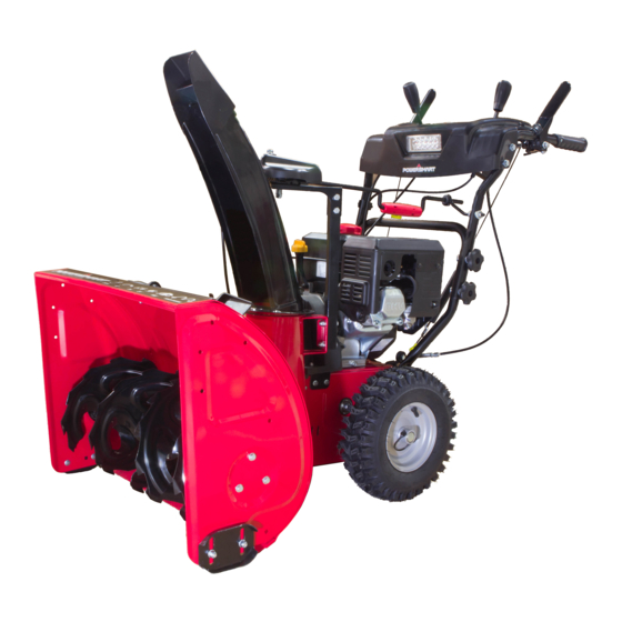
Page 10: Knowing Your Snow Thrower
KNOWING YOUR SNOW THROWER Use the illustrations below to become familiar with the locations and functions of the various components and controls of this snow thrower. Drive Control Handle Shave Plate Chute Deflector Lever Skid Shoe Auger Control Handle Tire Speed Control Handle Belt Cover Chute Rotation Handle... - Page 11 Drive Control Handle Located on the right side of the upper handle, the Drive Control Handle is used to engage and disengage the drive wheels. Squeeze the Drive Control Handle against the upper handle to engage the wheels; release to disengage. Speed Control Lever The Speed Control Lever is located in the center of the panel and is used to set the drive speed and direction of travel.
-
Page 12: Assembly And Adjustments
ASSEMBLY AND ADJUSTMENTS The following section describes steps necessary to prepare the snow thrower for use. If after reading this section, you are unsure about how to perform any of the steps please call (800) 791-9458 Mon-Fri 9-5 EST for customer service. Failure to perform these steps properly can damage the snow thrower or shorten its life. - Page 13 Step 2 – Chute assembly 1. Install the discharge chute onto the chute flange on the auger housing. The chute only rests on the flange. 2. Slide the chute rod through the mounting hole on the left upper handle. 3. Attach the chute rotation bar to the mount bracket onto the chute housing using two screws, washers and locknuts.
-
Page 14: Snow Thrower Preparation
SNOW THROWER PREPARATION PLEASE REFER TO ENGINE MANUAL (SEPARATE DOCUMENT) FOR ENGINE OPERATION INSTRUCTIONS. The following section describes steps to prepare your Snow Thrower for use. If after reading this section, you are unsure about how to perform any of the steps please call 1-800-791-9458 for customer service. Failure to perform these steps properly can damage your Snow Thrower or shorten its life. - Page 15 AUGER AND DRIVE CONTROLS 1. To engage the auger, press down on the auger control handle (left side handle). 2. To engage the drive, press down on the drive control handle (right side handle). The machine should start moving in the direction and speed that the speed control lever is set to. 3.
-
Page 16: Operating Your Snow Thrower
1. Loosen the knobs on the chute deflector and adjust the chute deflector to the desired angle. 2. Retighten the knobs. Do not over-tighten. OPERATING YOUR SNOW THROWER STARTING Please refer to ENGINE manual (separate document) for engine operation instructions. CLEARING SNOW Start the engine (see ENGINE manual) once your Snow Thrower has been running outside for several minutes, it is now ready for use. -
Page 17: Maintenance
STOPPING When finished using your Snow Thrower, perform the following steps to shut it down. 1. Engage the auger and impeller for 30 seconds to clear any remaining snow inside your Snow Thrower. 2. Stop the auger by releasing the left control handle. 3. - Page 18 SHAVE PLATE REPLACEMENT Remove both skid shoes and hardware including carriage bolts and nuts which attach shave plate to snow thrower housing. Reassemble new shave plate, making sure heads of the carriage bolts are to the inside of the auger housing. AUGER OR IMPELLER JAMS WARNING! The auger and impeller rotate at fast speeds Clean-out tool...
- Page 19 DRIVE SPEED CONTROL CABLE ADJUSTMENT WARNING! Entanglement Hazard – Use caution when performing the speed control cable adjustment. The speed control lever is connected to two cables that work in tandem to control machine speed and direction. As the speed control lever is moved from forward to reverse gears (right to left) one cable is pulled and one is pushed.
- Page 20 4. Left Side - Loosen the hex nuts attaching the auger housing to the main frame. 5. Right Side - Remove the hex nuts, lock washers and flat washers attaching the auger housing to the main frame. 6. Remove the belt from the drive pulley while pulling the right side of the auger housing away from the main frame just enough to access the belt and auger pulley.
- Page 21 WARNING! Ensure the belt cover is installed and all safety guards are in place before the engine is started and at all times when the engine or machine are operating. AUGER BELT AND RELATED COMPONENT INSPECTION When replacing your snow blower auger belt it is important to determine the cause of the failure (if applicable) and take corrective action to avoid repeated failure.
-
Page 22: Storage & Cleaning
STORAGE & CLEANING PROPER STORAGE PROCEDURES WARNING! Never store your Snow Thrower for extended periods of time with fuel in the tank or carburetor. Fuel stabilizer can be added to the fuel in can to extend its shelf life for storage. Store the unit in a locked, dry place out of the reach of children to prevent unauthorized use or damage. -
Page 23: Troubleshooting
TROUBLESHOOTING Problem Causes Remedy WARNING - Before attempting to make any inspections, repairs or adjustments, stop the engine, wait for all moving parts to stop moving and carefully disconnect the engine spark plug wire. If tipping or turning the snow blower is required for any inspection or repair, first wait until the engine is cool to the touch and then drain the engine of all fuel and oil into suitable containers and store or dispose of in a proper manner. - Page 24 Problem Causes Remedy Drive system Check drive belt tension pulley for damage or incorrect tension, repair as necessary. Replace No forward or Drive belt loose or damaged drive belt. reverse drive movement when Friction drive wheel is worn or damaged Replace friction drive wheel drive handle Allow snow blower to dry and or warm up or...
- Page 25 Problem Causes Remedy Auger System Auger tension pulley arm return spring broken or missing Replace tension arm return spring Auger tension pulley arm stuck or binding Repair or replace tension arm as necessary Auger tension pulley arm or pulley Repair, replace or align tension arm and or pulley misaligned or damaged as necessary Auger belt broken,...
-
Page 26: Exploded View And Parts List
EXPLODED VIEW AND PARTS LIST Panel Assembly (All Parts Number Begin with P) - Page 27 Item Stock # Description Item Stock # Description 303020106 Screw M8x20 303130074 Press Spring 303080306 Lower Handle 203050053 Cable Holder 303200060A Upper Auger Cable 203020380 Washer 303200018 Shift Cable Left 303070753 Bracket 303200019 Shift Cable Right 303020281 Screw M8x16 303200061A Upper Drive Cable 303020067 Bolt M8x55...
- Page 28 Frame Assembly (All Parts Number Begin with F)
- Page 29 Item Stock # Description Item Stock # Description 303020492 Screw M6x10 302090220 Left Wheel Assembly 303042001 Flat Washer 6 303123008 Bow Tie Cotter Pin 303160308 Spacer 303110022 Semicircular Key 303042039 Flat Washer 10 303070134A Guide Roller Bracket 303041015 Spring Washer10 303200012 Lower Auger Cable 303030068...
- Page 30 Auger Housing Assembly (All Parts Number Begin with H)
- Page 31 Item Stock # Description Item Stock # Description 303180424 Single Auger Assembly R 303030708 Locknut M10 202450076 Gear Housing Assembly 303043019 Butterfly Washer H02-1 303090031 Worm Gear Case R 303070126 Idler Arm H02-2 303020142 Bolt M8x10 303160175 Extension Spring H02-3 303070260 Gasket 303160172...
-
Page 32: Two (2) Years Limited Warranty
Limited Warranty, you must return the entire power tool product; transportation prepaid, to PowerSmart Include a legible copy of the original receipt, which lists the date of purchase (month and year) and the name of the company purchased from.
Need help?
Do you have a question about the DB7124 and is the answer not in the manual?
Questions and answers
What is the part number for the carburetor for a DB7124 snowblower