Table of Contents
Advertisement
INSTRUCTION MANUAL
27 inch Two Stage Gas Snow Thorwer
Model #DB7127
PROBLEMS? QUESTIONS?
CALL OUR CUSTOMER HELP
LINE 800-791-9458 Mon-Fri 9-5 E!tT
Have product questions or need technical support? Please feel free to contact us!
Website:
www .Amerisuninc.com
www.PowerSmartUSA.com
Toll free: 1-800-791-9458 Mon- Fri 9-5
EST Email: support@amerisuninc.com
Advertisement
Table of Contents

Related Manuals for Powersmart DB7127


Summary of Contents for Powersmart DB7127
- Page 1 INSTRUCTION MANUAL 27 inch Two Stage Gas Snow Thorwer Model #DB7127 PROBLEMS? QUESTIONS? CALL OUR CUSTOMER HELP LINE 800-791-9458 Mon-Fri 9-5 E!tT Have product questions or need technical support? Please feel free to contact us! Website: www .Amerisuninc.com www.PowerSmartUSA.com Toll free: 1-800-791-9458 Mon- Fri 9-5...
-
Page 3: Table Of Contents
35.lx28.8x31.lin Weight: 213.9lbs Thank you for purchasing PowerSmart products. It is crucial and highly recommended that you read this instruction manual in its' entirety, as this is an invaluable tool and reference point in understanding the operation of your unit. -
Page 4: Introduction
INTRODUCTION Thank you for purchasing a PowerSmart ® Product. This manual provides detailed information regarding the safe operation and maintenance of this product. Every effort has been made to ensure the accuracy of the information in this document. PowerSmart ®... -
Page 10: Knowing Your Snow Thrower
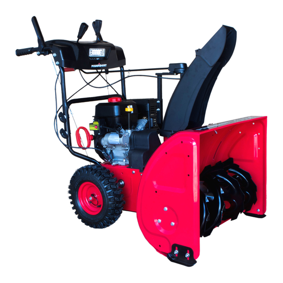
KNOWING YOUR SNOW THROWER Use the illustrations below to become familiar with the locations and functions of the various components and controls of this snow thrower. Drive Control Lever Skid Shoe Chute Deflector Control Wheel Tire Drive Speed/Gear Control Belt Cover Auger Control Lever Lower Handle Chute Rotation Handle... - Page 11 Fuel Tank Cap Switch Key Primer Bulb Choke Lever Drive Control Lever Located on the right side of the upper handle, the Drive Control Handle is used to engage and disengage the drive wheels. Squeeze the Drive Control Handle against the upper handle to engage the wheels; release to disengage.
-
Page 12: Assembly And Adjustments
ASSEMBLY AND ADJUSTMENTS The following section describes steps necessary to prepare the snow thrower for use. If after reading this section, you are unsure about how to perform any of the steps please call 800-791-9458 Mon - EST for customer service assistance. Failure to perform these steps properly can damage the snow thrower. - Page 13 4. Cut and remove all tie wraps that are on Cables, Frame Handles, Drive Control (Lever) & Auger Control (Lever). 5. Verify that the connection for the Upper & Lower Drive/Auger Cables is accurate. (See Figure 2) Figure 2 Step 2: Installing the Chute Assembly 1.
- Page 14 2. Attach Chute Handle to base of Chute Gear Connection and secure with Cotter Pin, as indicated on Figure 5. Figure 5 3. Verify that ALL cables are clear and not obstructing the Chute Handle operation of your snow thrower unit. (See Figure 6) Figure 6 Step 4 –...
-
Page 15: Snow Thrower Preparation
SNOW THROWER PREPARATION PLEASE REFER TO ENGINE MANUAL (SEPARATE DOCUMENT) FOR ENGINE OPERATION INSTRUCTIONS. The following section describes steps to prepare your snow thrower for use. If after reading this section, you are unsure about how to perform any of the steps please call 1-888-980-4937 for customer service. Failure to perform these steps properly can damage your snow thrower or shorten its life expectancy. - Page 16 AUGER AND DRIVE CONTROLS 1. To engage the auger (blades), press down on the auger control lever (left side handle). 2. To engage the drive, press down on the drive control lever (right side handle). The machine should start moving in the direction and speed for the respective setting on the speed/gear control. 3.
-
Page 17: Operating Your Snow Thrower
OPERATING YOUR SNOW THROWER STARTING Please refer to ENGINE manual (separate document) for engine operation instructions. CLEARING SNOW Start the engine (see ENGINE manual) once your snow thrower has been running outside for several minutes, it is now ready for use. Make sure the path in front of your Snow Thrower is free from people, animals, objects, and all other obstructions except for snow. -
Page 18: Maintenance
MAINTENANCE WARNING! Never perform maintenance while your snow thrower is running. Turn OFF the engine before performing any maintenance tasks on your Snow Thrower. Proper maintenance of your snow thrower will help prolong its life. Please perform the following maintenance procedures as required. Please read the ENGINE manual for engine maintenance procedures. - Page 19 4. Wait until the auger and impeller have come to a full stop. 5. Clear any visible jams using the clean out tool attached to your machine. WARNING! DO NOT try to clear jams with your hands or feet. AUGER SHEAR PINS REPLACEMENT Shear pins are used to attach the auger shaft to the auger blades.
- Page 20 middle position between these two settings is neutral (there is no actual neutral "notched" position on the control panel). 1. With the engine running engage the drive control handle and move the speed control lever between 1 and R1 to determine which way the cables need to be adjusted. Release the drive control handle when shifting between gears.
- Page 21 AUGER BELT INSTALLATION WARNING! Entanglement Hazard – Before performing any service procedures, make sure the engine is off and remove the spark plug wire from the spark plug to ensure the engine cannot accidently start. 1. Push the auger tension pulley arm to move the auger brake to allow access for installation of the belt into the auger pulley.
-
Page 22: Storage & Cleaning
• Misaligned tension pulley, the pulley should move parallel to the belt centered to the belt • Check return spring operation and tension Inspect the auger control lever (handle) and cable: • Cable and connection damage • Free movement (from engage to disengaged positions) •... -
Page 23: Troubleshooting
TROUBLESHOOTING Problem Causes Remedy WARNING - Before attempting to make any inspections, repairs or adjustments, stop the engine, wait for all moving parts to stop moving and carefully disconnect the engine spark plug wire. If tipping or turning the snow blower is required for any inspection or repair, first wait until the engine is cool to the touch and then drain the engine of all fuel and oil into suitable containers and store or dispose of in a proper manner. - Page 24 Problem Causes Remedy Drive system Check drive belt tension pulley for damage or incorrect tension, repair as necessary. Replace No forward or Drive belt loose or damaged drive belt. reverse drive movement when Friction drive wheel is worn or damaged Replace friction drive wheel drive handle Allow snow blower to dry and or warm up or...
- Page 25 Problem Causes Remedy Auger System Auger tension pulley arm return spring broken or missing Replace tension arm return spring Auger tension pulley arm stuck or binding Repair or replace tension arm as necessary Auger tension pulley arm or pulley Repair, replace or align tension arm and or misaligned or damaged pulley as necessary Auger belt broken,...
-
Page 26: Exploded View And Parts List
EXPLODED VIEW AND PARTS LIST Panel Assembly... - Page 27 Item Stock # Description Item Stock # Description Hex Flange 303020493 303042023 Flat washer Washer Screw 303080539 Lower tube 303043010 Washer 303020139 T-screw 303030036 Locknut Upper handle 303043010 Washer 29 303180697A assembly 203020865A Knob (black) 203020881 Rubber Washer 303030026 303010237 Screw Upper Auger 303200061A 203070009 Handle bar grip...
- Page 28 Chute Assembly...
- Page 29 Item Stock # Description Item Stock # Description 303020275 Bolt M8x40 303130339 Clip 303041022 Spring Washer 8 303160737 Cutter Pin 303042023 Flat washer 8 303050032 Snap Ring 13 303080523 Support Tube 303042130 Flat Washer 13 303010176 Screw 303010270 Screw 4x14 Discharge Chute Steering Gear 203010820...
- Page 30 Frame Assembly...
- Page 31 Item Stock # Description Item Stock # Description 303122002 Dowel Pin Loncin BYO Flat key 13"Wheel 303060041 Small synchronous pulley 302090221 Assembly Left 13"Wheel 302090220 303060060 Bush Assembly Right 203050140 Spacer bush 303160432 Bolt 303050028 Shaft ring 303020154 Step bolt 303160140 Gear wheel 303130094...
- Page 32 203020364 Guide Roller 303180037 Drive Bracket 303030032 Nylon Locknut 303130073 Extension Spring Guide Roller 303070134A 303130072 Extension Spring Bracket 303070206 Cable Bracket 303180274A Friction Disk Bracket 303030032 Nylon Locknut 303030068 203020364 Guide Roller 303041015 Spring washer 303160177 Screw 303042004 Flat washer Guide Roller Friction disc support shaft 303070418A...
- Page 33 Auger Housing Assembly...
- Page 34 Item Stock # Description Item Stock # Description 303020245 Hex Flange Screw 303030076 Plain Nuts 303070234 Bearing Housing 303071061 27“Shave (186C red) Hex Flange 203060013 303020542 Square Neck Bolt Bearings (plastic) 27”Auger Housing 203050109 Spacer bush 303180954 Assembly (186C red) 203060012 Flange Bushing 303020166 Square Neck Bolt...
-
Page 35: Two(2)Years Limited Warranty
1-800-791-9458 (M-F 9 am-5pm EST)
Need help?
Do you have a question about the DB7127 and is the answer not in the manual?
Questions and answers