Advertisement
Questions, problems, missing parts?
Amerisun customer service department at 1-800-791-9458 or visit Amerisuninc.com or e-mail
support@amerisuninc.com. For engine related problems, questions and warranty service call the engine
manufacturer 1-877-274-2214.
WARNING! Read and follow all safety rules and instructions in this manual before attempting to operate this
machine. Failure to comply with these instructions may result in personal injury. Save these instructions. This
unit is equipped with an internal combustion engine and may spark resulting in fire or explosion if used near
combustible material or fluid. Only use when the engine's exhaust system is equipped with a spark arrester
meeting applicable local or state laws (if any). The spark arrester shall be maintained in effective working
order by operator.
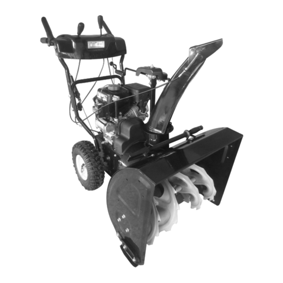
TWO STAGE GAS SNOW THROWER
If you have questions or need technical support, call the
MODEL DB7103-24 and 26
Advertisement
Table of Contents

Related Manuals for Powersmart DB7103-24


Summary of Contents for Powersmart DB7103-24
- Page 1 TWO STAGE GAS SNOW THROWER MODEL DB7103-24 and 26 Questions, problems, missing parts? If you have questions or need technical support, call the Amerisun customer service department at 1-800-791-9458 or visit Amerisuninc.com or e-mail support@amerisuninc.com. For engine related problems, questions and warranty service call the engine manufacturer 1-877-274-2214.
-
Page 2: Table Of Contents
TABLE OF CONTENTS Safety............................... 2 Feature Identification ..........................5 Box Contents ............................6 Assembly ..............................6 Operation ..............................8 Operating Your Snow Thrower ....................... 11 Recommended Maintenance Schedule ....................11 Troubleshooting ............................20 Warranty ..............................24 Safety Symbols This page depicts and describes safety symbols that may appear on this product. Read,understand and follow all instructions on the machine before attempting to assemble and operate. -
Page 3: Safety
SAFETY Preparation Thoroughly inspect the area where the This symbol points out important safety equipment is to be used. Remove all doormats, instructions which, if not followed, could newspapers, sleds, boards, wires ,branches and endanger the personal safety and or other foreign object, which could be tripped over or property of yourself and others. - Page 4 Service The auger impeller control lever is a safety device. Stop the engine before making any adjustments. Never bypass its operation. Doing so makes the Check for misalignment, breakage of or binding of machine unsafe and may cause personal injury. moving parts, and any other conditions that may The control levers must operate easily in both affect operation.
- Page 5 When staring engine, pull cord slowly until Have the machine inspected annually by an resistance is felt, then pull rapidly, Rapid retraction authorized service dealer to ensure that all of starter cord (kickback) will pull hand and arm mechanical and safety systems are working toward engine faster then you can let go.
-
Page 6: Feature Identification
FEATURE IDENTIFICATION TECHNICAL SPECIFICATIONS Clearing Width: DB7103 24 and 26 inches Clearing Height: 21 inches 6 Forward and 2 Reverse Speeds Engine Displacement: 208cc, 4 stroke A - Drive Control Handle E - Engine I - Snow/Ice Clean Out Tool B - Speed Control Lever F - Skid Shoe J - Chute Assembly... -
Page 7: Box Contents
A. Drive Control Handle K. Chute Deflector Lever Located on the right side of the upper handle, the The angle of the chute deflector controls the Drive Control is used to engage and disengage discharge distance of the snow. Raising the the drive wheels. - Page 8 Chute Assembly 1. Install the discharge chute onto the chute flange on the housing. The chute only rests on the flange. 2. Attached the upper handle to the lower handle using four (4) knobs, washers and bolts. Slide the chute crank rod through the mounting hole on the left upper handle.
-
Page 9: Operation
OPERATION NOTICE: Make sure all fasteners are tightened before starting the machine. PLEASE REFER TO ENGINE MANUAL (SEPARATE DOCUMENT) FOR ENGINE Skid Shoe Installation and OPERATION INSTRUCTIONS. Adjustment The following section describes steps to prepare 1. Locate the pair of skid shoes from parts bag your Snow Thrower for use. - Page 10 Start your clearing path by throwing snow in a back NOTICE: If you are unsure about the assembly or and forth motion. To clear in the opposite direction, condition of any of your Snow Thrower parts, stop your Snow Thrower and pivot it on its wheels to please call customer service department.
- Page 11 Drive Speed Control Lever Chute Discharge Angle Adjustment WARNING! Always disengage the drive and Move the drive speed control lever to the desired auger control handles before making speed. There are eight ( 8 ) s ettings:six (6) forward adjustments. Make sure the augers are speeds and two (2) reverse speeds.
-
Page 12: Operating Your Snow Thrower
OPERATING YOUR SNOW move or throw. Wet snow will tend to clog and stick more to the augers and chute. Keep the THROWER auger engaged as much as possible when clearing wet snow to help prevent clogging. Starting WARNING! If snow is filled with foreign material, damage to the snow thrower may Please refer to ENGINE manual (separate result. - Page 13 WARNING! DO NOT OVER-INFLATE THE Check the bolts at frequent intervals for proper TIRES. Over-inflating could cause a tire to tightness to ensure that the equipment is in safe burst and cause severe bodily injury. working condition. Shave Plate Replacement After each snow removal session, run the Snow Remove both skid shoes and hardware including Thrower for a few minutes to prevent the...
- Page 14 Checking auger gear box oil level Drive Control Cable Tension Adjustment Service yearly-check the auger gear box oil and add oil if necessary WARNING! Entanglement Hazard - Before 1. Clean area around pipe plug performing any adjustment procedures, make 2. Remove pipe plug from top of gear box sure the engine is off and remove the spark 3.
- Page 15 To adjust the cables one cable should be moved 4. Adjustment is made by changing the position up and the other down equally in their respective of the lower cable in the adjustment plate brackets until there is a positive direction change holes (1 to 9).
- Page 16 Auger Belt Tension Adjustment The auger cable is located on the left side (when standing behind the snow blower) and is made WARNING! Entanglement Hazard - Before up of an upper and lower cable connected by an performing any adjustment procedures, make adjustment plate.
- Page 17 4. Adjustment is made by changing the position of the lower cable in the adjustment plate holes (1 to 9). O nly move the lower cable diagonally one hole at a time from its original 2. Remove 2 hex head screws and remove belt position.
- Page 18 5. Right Side - Remove the hex nuts, lock 7. Push the auger tension pulley arm to move washers and flat washers attaching the auger the auger brake, away from the belt to allow housing to the main frame. removal of the belt. 6.
- Page 19 2. Push the auger tension pulley arm to move the auger brake to allow access for installation of the belt into the auger pulley. Note: The belt guide pin helps keep the belt in the pulley when the belt is disengaged. The pin should not be tight to the belt.
- Page 20 Auger Belt and Related Component Free movement (from engage to disengaged positions) Inspection Binding or improperly routed cable When replacing your snow blower auger belt it is Cable pulley(s) damage, misalignment and binding important to determine the cause of the failure (if Cable adjustment plate damaged or improper applicable) and take corrective action to avoid installation...
-
Page 21: Troubleshooting
TROUBLESHOOTING Problem Possible Causes Remedy WARNING-Before attempting to make any inspections, repairs or adjustments, stop the engine, wait for all moving parts to stop moving and carefully disconnect the engine spark plug wire. If tipping or turning the snow blower is required for any inspection or repair, first wait until the engine is cool to the touch and then drain the engine of all fuel and oil into suitable containers and store or dispose of in a proper manner. - Page 22 Cooling air flow Remove air flow restrictions from engine restricted to engine Check oil level on dipstick. If oil is not visible on dipstick, check oil level using LOWER fill plug BEFORE adding oil. Oil Engine should be visible and to the top 2 Overheats threads of LOWER fill plug(not the Low oil level...
- Page 23 Drive System Drive control cable loose, Repair or adjust drive control cable adjust tension. broken or binding See Auger and Drive Cable Adjustment. Check drive belt tension pulley for damage or 2 Drive belt loose or damaged incorrect tension, repair as necessary. Replace drive belt.
- Page 24 Impeller not connected to impeller shaft, impeller or shaft 9 Replace roll pins or impeller as necessary damaged or roll pins broken Ingest an adequate amount of snow to 10 Inadequate amount of snow allow snow to compact enough to be moved through augers and into impeller.
-
Page 25: Warranty
This warranty covers product defects only. Neither Amerisun nor LCT Engine Corporation is liable for indirect, incidental, or consequential damages in connection with the use of PowerSmart Products covered by this warranty, including any cost or expense of providing substitute equipment or service during reasonable periods of mal-function or non-use pending completion of repairs under this warranty.
Need help?
Do you have a question about the DB7103-24 and is the answer not in the manual?
Questions and answers