
Related Manuals for Powersmart DB7622E


Summary of Contents for Powersmart DB7622E
- Page 1 INSTRUCTION MANUAL 22 inch Two Stage Gas Snow Thrower Model # DB7622E Have product questions or need technical support? Please feel free to contact us! Website: www.Amerisuninc.com Toll free: 1-800-791-9458 Mon-Fri 9-5 EST Email: support@amerisuninc.com...
- Page 3 Storage & Cleaning…………...…………………………………………. Troubleshooting…………………………………………………………. Exploded view and parts list……………………………………………... 28 Two (2) years limited warranty……………………...…………………… 33 TECHNICAL DATA 22 inch Two Stage Snow Thrower Model #: DB7622E Engine: 212cc Snow Engine Engine oil Capacity: 20 fl.oz Fuel Tank Capacity: 0.66 Gallon...
- Page 4 INTRODUCTION ® Thank You for Purchasing a PowerSmart Product. This manual provides information regarding the safe operation and maintenance of this product. Every effort has been made to ensure the accuracy of the ® information in this manual. PowerSmart reserves the right to change this product and specifications at any time without prior notice.
- Page 5 TRAINING Read, understand, and follow all instructions on the machine and in the manual(s) before attempting to assemble and operate. Keep this manual in a safe place for future and regular reference. • Be familiar with all controls and their proper operation. Know how to stop the machine and disengage them quickly.
- Page 6 • Read, understand and follow all instructions on your Snow Thrower and in this Operator's Manual before attempting to assemble and operate your machine. • Keep this manual in a safe place for future and regular reference. If replacement parts are needed, refer to the manual.
- Page 7 • Never store the machine or fuel container inside where there is an open flame, spark or pilot light (e.g. furnace, water heats, space heater, clothes dryer etc.). • Allow machine to cool at least 5 minutes before storing. • Never fill containers inside a vehicle or on a truck or trailer bed with a plastic liner.
- Page 8 • Disengage power to the auger impeller when transporting or not in use. • Never operate machine at high transport speeds on slippery surfaces. Look down and behind and use care when backing up. • If the machine should start to vibrate abnormally, stop the engine, disconnect the spark plug wire and ground it against the engine.
- Page 9 • Check control levels periodically to verify they engage and disengage properly and adjust, if necessary. Refer to the adjustment section in this operator's manual for instructions. • Maintain or replace safety and instruction labels, as necessary. • Observe proper disposal laws and regulations for gas, oil, etc. to protect the environment. •...
-
Page 10: Table Of Contents
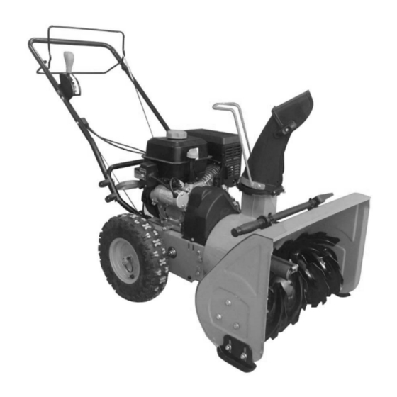
KNOWING YOUR SNOW THROWER Use the illustrations below to become familiar with the locations and functions of the various components and controls of this snow thrower. Auger Control Handle Clean-out Tool Speed Control Lever Belt Cover Fuel Tank Cap Recoil Starter Handle Oil Dipstick Electric starter Chute Rotation Handle... -
Page 11: Auger Control Handle
Auger Skid Shoe Shave Plate Auger Housing Shear Pin Tire Drive Control Handle The Drive Control Handle is used to engage and disengage the drive wheels. Pull up on the Drive Control Handle to engage the wheels; release to disengage. Speed Control Lever The Speed Control Lever is located in the right side and is used to set the drive speed and direction of travel. -
Page 12: Discharge Chute
Position the shoes based on the surface conditions. Adjust upward for hard-packed snow. Adjust downward when operating on gravel or crushed rock surfaces. Auger When engaged, the augers rotate to cut snow and direct it into the impeller housing to be discharged out the chute. - Page 13 ASSEMBLY AND ADJUSTMENTS The following section describes steps necessary to prepare the snow thrower for use. If after reading this section, you are unsure about how to perform any of the steps please call (800) 791-9458 Mon-Fri 9-5 EST for customer service. Failure to perform these steps properly can damage the snow thrower or shorten its life.
- Page 14 Step 2 – Attach Auger and Drive Cables 1. Push drive control handle inward to detach from the upper handle. 2. Attach drive cable to the hole on drive control handle bar. 3. Re-attach drive control handle to the upper handle. 4.
- Page 15 Step 3 – Chute assembly 1. Loosen and remove the three sets of screws, locknuts and washers on the discharge chute. 2. Hold the discharge chute and handle to align the mounting holes to chute base mount holes. Insert the screws and washers and secure with locknuts.
- Page 16 SNOW THROWER PREPARATION PLEASE REFER TO ENGINE MANUAL (SEPARATE DOCUMENT) FOR ENGINE OPERATION INSTRUCTIONS. The following section describes steps to prepare your Snow Thrower for use. If after reading this section, you are unsure about how to perform any of the steps please call 1-800-791-9458 for customer service. Failure to perform these steps properly can damage your Snow Thrower or shorten its life.
-
Page 17: Drive Control Handle
AUGER AND DRIVE CONTROLS 1. To engage the auger, push back the auger control handle; release to disengage. 2. To engage the drive, pull up on the drive control handle. The machine should start moving in the direction and speed that the speed control lever is set to. 3. - Page 18 CHUTE DISCHARGE ANGLE ADJUSTMENT WARNING! Always disengage the drive and auger control handles before making adjustments. Make sure the augers are stopped and the machine is not moving. The angle of the chute deflector controls the discharge distance of the snow. Raising the angle will increase the distance.
- Page 19 OPERATING YOUR SNOW THROWER STARTING Please refer to ENGINE manual (separate document) for engine operation instructions. CLEARING SNOW Start the engine (see ENGINE manual) once your Snow Thrower has been running outside for several minutes, it is now ready for use. Make sure the path in front of your Snow Thrower is free from people, animals, objects, and all other obstructions except for snow.
- Page 20 Use the supplied snow clean out tool to clear the obstruction. After unclogging, wipe the tool clean, and place it in the holder on top of the auger housing. MAINTENANCE WARNING! Never perform maintenance while your Snow Thrower is running. Turn OFF the engine before performing any maintenance tasks on your Snow Thrower.
- Page 21 2. Keep hands and feet away from rotating parts while the engine is running. 3. Do not wear loose fitting clothing that can become entangled in rotating parts. 4. Wait until the auger and impeller have come to a full stop. 5.
- Page 22 which way the cables need to be adjusted. Release the drive control handle when shifting between gears. 2. Loosen the jam nuts on each cable (only one or two threads) and move each cable up and down as required until a positive direction change is achieved when the lever is shifted between F1 and R1. This may take multiple attempts to find the exact setting.
- Page 23 AUGER BELT INSTALLATION WARNING! Entanglement Hazard – Before performing any service procedures, make sure the engine is off and remove the spark plug wire from the spark plug to ensure the engine cannot accidently start. 1. Push the auger tension pulley arm to move the auger brake to allow access for installation of the belt into the auger pulley.
- Page 24 AUGER BELT AND RELATED COMPONENT INSPECTION When replacing your snow blower auger belt it is important to determine the cause of the failure (if applicable) and take corrective action to avoid repeated failure. Inspect the belt: • Correct size and type •...
- Page 25 TROUBLESHOOTING Problem Causes Remedy WARNING - Before attempting to make any inspections, repairs or adjustments, stop the engine, wait for all moving parts to stop moving and carefully disconnect the engine spark plug wire. If tipping or turning the snow blower is required for any inspection or repair, first wait until the engine is cool to the touch and then drain the engine of all fuel and oil into suitable containers and store or dispose of in a proper manner.
- Page 26 Problem Causes Remedy Drive system No forward or reverse Drive belt loose or damaged Check drive belt tension pulley for damage or incorrect drive movement when tension, repair as necessary. Replace drive belt. drive handle engaged Friction drive wheel is worn or Replace friction drive wheel damaged Friction drive wheel wet or slipping...
- Page 27 Problem Causes Remedy Auger System Auger belt broken, or Auger tension pulley arm return spring Replace tension arm return spring repeated failure broken or missing Auger tension pulley arm stuck or Repair or replace tension arm as necessary binding Auger tension pulley arm or pulley Repair, replace or align tension arm and or pulley as misaligned or damaged necessary...
Need help?
Do you have a question about the DB7622E and is the answer not in the manual?
Questions and answers