
Related Manuals for Universal Robots CB Series

Summary of Contents for Universal Robots CB Series
- Page 1 UR Startup Guide CB-Series (Teach Mode) ........© COPYRIGHT READY Robotics ALL RIGHTS RESERVED ........1...
-
Page 2: Table Of Contents
Table of contents: UR CB-Series (Teach Mode) Hardware Reqs Software Reqs How to Check Software Reqs Wiring the READY Pendant Connecting the Controller to the IPC Powering On Configuring Polyscope Signing Into ForgeOS Getting Config Files Transferring Config Files Finishing Device Configuration ........ -
Page 3: Ur Cb-Series (Teach Mode)
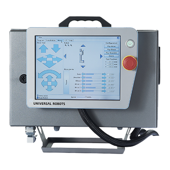
UR CB-Series (Teach Mode) Hardware Reqs Image Name Description Robot Control Box and Controls the robot in its native Pendant software. Hosts ForgeOS. See requirements if you are not using a Forge/Hub or the legacy Forge/Ctrl. Touch-screen interface for READY Pendant ForgeOS. - Page 4 Image Name Description Cat5e Bulkhead Attaches at the base of the UR Ethernet Connector Control Box to connect two (Mouser, 1546413-3) Ethernet cables. Routes from the internals of the UR Control Box to the Cat5e Bulkhead Cat5e Shielded Ethernet Connector, routes from Ethernet Cables (x3) the Cat5e Bulkhead Ethernet Connector to the IPC, and connects...
-
Page 5: Software Reqs
Image Name Description Transfers configuration files from USB Flash Drive ForgeOS to the robot controller. Software Reqs The native UR software that runs on the UR Teach pendant is called Polyscope. Refer to the table below for the Polyscope version requirement. Requirement Version Controller Software Version... - Page 6 3. In the Version tab, look for the Universal Robots Software version. 4. If your UR software is older than the requirement, download an update at the Universal Robots Support site: INFO If you have a CB-Series robot with an old Polyscope version, you may need to update sequentially before jumping to the latest version.
-
Page 7: Wiring The Ready Pendant
Even though you can update Polyscope versions, downgrading Polyscope versions will likely cause issues. Don't upgrade Polyscope beyond the required version for ForgeOS. Wiring the READY Pendant The READY pendant includes 3 safety outputs: 1. Key Swtich 2. 3-Position Enabling Switch 3. - Page 8 Remove an unused rubber plug or metal knockout on the the UR Control Box. Insert a cable gland into the hole........© COPYRIGHT READY Robotics ALL RIGHTS RESERVED ........8...
- Page 9 INFO This cable gland will maintain IP rating and provide strain relief to the safety cable. Route the READY pendant flying leads to the UR Control Box. For wiring instructions, select which IPC you are using: General IPC Forge/Hub (Legacy) Forge/Ctrl Connect the READY pendant's Ethernet cable to the IPC.
- Page 10 in the table. Include ferrules at the end of your wiring to insert in the terminal blocks. Safety Configurable Exterior 24V Pendant Cable Function Block Input Block Power Supply Enabling Switch Brown (Optional) 24V Circuit 1 Enabling Switch Yellow (Optional) CI0 Circuit 1 Enabling Switch Green...
-
Page 11: Connecting The Controller To The Ipc
Safety Configurable Exterior 24V Pendant Cable Function Block Input Block Power Supply White Key Switch Blue Key Switch Circuit 2 (NC) Circuit 2 (NC) White/Blue INFO Leave the Safeguard Stop terminals jumpered if you're not using them. Make sure the SI0 terminal is jumpered to the 24V terminal above it and the SI1 terminal is jumpered to the 24V terminal above it. - Page 12 3. On the UR Control Box, remove another rubber plug or metal knockout. 4. Insert the silver side of the Ethernet Connector into the hole. 5. Find the nut that you removed from the Ethernet Connector. Screw the nut onto the Connector until it is handtight against the Control Box wall.
- Page 13 7. Plug the other end of the cable into the Ethernet port in the UR controller........© COPYRIGHT READY Robotics ALL RIGHTS RESERVED ........13...
- Page 14 8. Plug one end of the longer Ethernet cable into the outside end of the Ethernet Connector........© COPYRIGHT READY Robotics ALL RIGHTS RESERVED ........14...
- Page 15 9. Plug the other end of the Ethernet cable into a LAN port on your IPC. 10. Plug the robot's cable connector into the metal socket at the base of the UR Control Box. Push the cable against the socket and turning the collar clockwise........
-
Page 16: Powering On
11. Plug the UR control box power cable into the port at the base of the UR Control Box. 12. Close the UR Control Box and turn the key counterclockwise to lock the door shut. Powering On 1. Plug the controller into a power source and turn it on........ -
Page 17: Configuring Polyscope
NOTE Follow the manufacturer's instructions for powering the controller. 2. Plug your IPC's power cable into a power outlet and turn it on. 3. If there are issues, power off each device, disconnect from power supplies, and check your wiring. Configuring Polyscope Move the UR robot to a safe position close to the base of the robot. - Page 18 INFO Remove the end effector to position the robot without causing a protective stop. After setting the default payload and TCP, re-attach the end effector, then initialize the robot arm. If you don't know how to move the UR robot with the UR pendant, refer to UR documentation.
- Page 19 Tap Configure TCP........© COPYRIGHT READY Robotics ALL RIGHTS RESERVED ........19...
- Page 20 Set your Tool Center Point (TCP), payload, and center of gravity. The settings save when you tap Exit. INFO The TCP is where the end effector interacts with the rest of the workcell. INFO The payload is the amount of weight attached to the end of the robot. Make sure that you account for the weight of your end effector and the weight of any parts that it will grab.
- Page 21 Tap ON to enable the servos. The green dot turns yellow to indicate that the robot is idle........© COPYRIGHT READY Robotics ALL RIGHTS RESERVED ........21...
- Page 22 Tap START to release the brakes. The robot will make some clicking sounds and small movements. CAUTION Make sure that the robot arm is not touching an object (e.g., a table). A collision between the robot arm and an obstacle might damage a joint gearbox........
- Page 23 Press OK in the bottom-right corner to apply the initialization........© COPYRIGHT READY Robotics ALL RIGHTS RESERVED ........23...
- Page 24 Change the network settings to connect with ForgeOS: Tap Network........© COPYRIGHT READY Robotics ALL RIGHTS RESERVED ........24...
- Page 25 Tap Static Address........© COPYRIGHT READY Robotics ALL RIGHTS RESERVED ........25...
-
Page 26: Signing Into Forgeos
Set the IP Address to 192.168.1.20 and set the Subnet Mask to 255.255.255.0. NOTE If you are using the legacy Forge/Ctrl, set the IP Address to 172.16.255.251 instead. Tap Apply. Signing Into ForgeOS INFO ........© COPYRIGHT READY Robotics ALL RIGHTS RESERVED ........26... - Page 27 If you need to install ForgeOS on your IPC, stop here and follow the installation instructions, then come back to these steps. The READY pendant automatically finds and pairs with the IPC. The three LEDs on the screen help you track the status: Pendant Network Connection: This condition is satisfied when the READY pendant has a valid network connection (i.e., the Ethernet cable is plugged in).
- Page 28 When a condition is in the process of becoming satisfied, a spinner around a ForgeOS logo appears to the right of the text. When a condition becomes satisfied, the LED turns green. If the READY pendant spends more than 60 seconds on any step, troubleshooting text displays.
- Page 29 ........© COPYRIGHT READY Robotics ALL RIGHTS RESERVED ........29...
-
Page 30: Getting Config Files
If ForgeOS is inactive, it opens the Settings app and prevents you from opening other apps. If you see the screen below, follow this. Getting Config Files Open the Device Configuration app........© COPYRIGHT READY Robotics ALL RIGHTS RESERVED ........30... - Page 31 Tap New+ to open the Device Library. Find your robot option in the Device Library and tap NEXT. Use the Filter by dropdown to show only robots on the list. Select your controller model, then select your robot model. If applicable, also select your safety configuration.
- Page 32 Insert a USB drive into the IPC. Tap Start Transfer ........© COPYRIGHT READY Robotics ALL RIGHTS RESERVED ........32...
-
Page 33: Transferring Config Files
Wait for the transfer to finish, then remove the USB drive. Transferring Config Files Insert the USB drive into the USB port of the UR pendant........© COPYRIGHT READY Robotics ALL RIGHTS RESERVED ........33... - Page 34 On the UR pendant home screen, tap Program Robot........© COPYRIGHT READY Robotics ALL RIGHTS RESERVED ........34...
- Page 35 In the File menu in the upper-right corner, tap Load Program........© COPYRIGHT READY Robotics ALL RIGHTS RESERVED ........35...
- Page 36 In the Current Directory of “/programs”, tap usbdisk. Tap forge-os........© COPYRIGHT READY Robotics ALL RIGHTS RESERVED ........36...
- Page 37 Tap ready-universal-robots-driver. Select ForgeOS.urp. Then tap Open. If you see a pop-up that reads, “Installation file could not be found. Would you like to use the currently loaded installation?”, tap YES. In the File menu, tap Save As........© COPYRIGHT READY Robotics ALL RIGHTS RESERVED ........37...
-
Page 38: Finishing Device Configuration
In the upper-right corner, tap the Home button (the middle icon). This returns the Current Directory to “/programs”. Tap Save. The pendant returns to the screen shown below. Finishing Device Configuration In ForgeOS, finish entering your robot device information: ........© COPYRIGHT READY Robotics ALL RIGHTS RESERVED ........38... - Page 39 Give your device a name. For the IP Address, enter 192.168.1.20 or the IP address you assigned to the robot, if different. Tap SAVE. ForgeOS attempts to connect with the robot controller for up to 20 seconds. INFO If the robot controller fails to connect, you see this pop-up........
- Page 40 Click DISMISS, do the following, then try to tap SAVE again: Check the Ethernet connection between the robot controller and IPC. Check the network settings on the robot controller. Check if the robot controller is on and in the correct operating mode (in auto or remote mode).
- Page 41 INFO View more info of TCPs and Payloads here. Set up the robot controller's Input/Output (IO) signals for use in the Device Control app and Task Canvas. You can come back to this later by editing the device's configuration. Tap SAVE to finish robot configuration.
- Page 42 NOTE To use these I/O signals, integrate your I/O devices with the robot controller........© COPYRIGHT READY Robotics ALL RIGHTS RESERVED ........42...
Need help?
Do you have a question about the CB Series and is the answer not in the manual?
Questions and answers