Advertisement
Quick Links
ENGLISH
DOORRAD/STA
User manual (original)
The symbols below indicate dangers.
Disregarding this symbol may result in
WARNING
serious injury or death.
Other symbols to be aware of.
Special attention is required when this symbol is
Note
shown.
This symbol shows a situation
This symbol shows a situation which
you should be aware of.
which should be avoided.
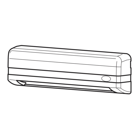
1. DESCRIPTION
Cover
Connector
Potentiometer
Mounting
Dip
Screws
(Sensitivity Volume)
Switch
(2 pcs.)
LED
Area
Detection
indicator
Mask
Window
Body
Base
3. MOUNTING PRECAUTIONS
CAUTION
To prevent malfunction mount as indicated.
1. Mount lower than 3m
2. Ensure nomoving objects
3. Mount where no direct
are in the detection area
and reflected sunlight shine
onto the sensor
3.0m
4. Mount where rain or snow
5. Install in vibration free
will not fall directly on unit.
environment
If the sensor is exposed to
excessive rain or snow, protect it with a Hotronwe
ather cover.
4. TECHNICAL SPECIFICATIONS
Model Name
DOORRAD/STA
Detection Method
Active Infrared Reflection
Installation Height
3.0 [m]
Available
Sensitivity adjustment
Depth adjustment
Angle
Row
R4~R1
0 to 5[degrees]
Width adjustment
Wide / Narrow
Presence Timer
R1, R2
30 [s]
R3, R4
Frequency
2 Frequencies
Monitor mode
Normal / Snow
Standby
(Green)
R4 Detecting
(Blue)
R3 Detecting
(Red)
R2 Detecting
(Slow flashing red)
R1 Detecting
(Fast flashing red)
Door movement is detected
(Orange)
LED Indicator
Indicates a change of dip switch settings (Fast flashing orange)
Internal sensor error
(Fast flashing green/red)
Reflected infrared signal from the floor is very low
(Flashing green/red)
Standard rispettati:
DIN18650-1:2005
EN12978:2003 - EN16005:2012
Esame CE di tipo 44 205 12 414283-001
Disregarding this symbol may result in
CAUTION
injury or damage to equipment.
Setting required conform with EN16005.
E N16005
This symbol shows an instruction
which must be followed.
2. EXTERNAL DIMENSIONS
75(Standard Mounting Pitch)
Accessories
15
35
10
Cable
Mounting Template
User Manual
210
In the following cases, the sensor may
detect without the presence of a person
1. A ccumulation of snow or
2. Environment is humid or
water on the floor.
steamy.
3. Objects placed in the
4. Pets / A nimals enter the
detection area.
detection area.
Supply Voltage
AC/DC 12~24 [V] ± 10% 50/60 [Hz]
AC12V : 1.1[VA]Max AC24V : 1.3[VA]Max
Power Consumption
DC12V : 70 [mA]Max DC24V : 40 [mA]Max
Safety
FormA Relay Contact
(R1,R2)
DC50[V] 0.1[A] (Resistance load)
Output
Activation
FormA Relay Contact
(R2,R3,R4)
DC50[V] 0.1[A] (Resistance load)
TEST imput
DC24V:6 [mA] Max
2 [s]
Output holding time
Approx 0.5 [s]
Response Time
0.1 ~ 0.2 [s]
Operating Temperature
-20 ~ +60 [˜ ]
Operating humidity
Below 80 [%]
IP Rate
IP54 (With Base)
Weight
Approx 180 [g]
Color
S : Silver , BL : Black
2 , performance level D according to
Category
EN ISO 13849-1:2015
Specificationmay changewithout prior notice.
5. MOUNTING & WIRING INFORMATION
WARNING
1. Determine the
mounting position
of the device and
attach the Mounting
Template. Drill the
mounting andwiring holes.
6-1. Wiring to a door controller that can test the sensor.
Red
Sensor's
Black
Cable
cable
White
Green
Yellow
Blue
Gray (+)
ON
Brown(+)
8
Set " TEST Input" dip switch setting 8 to "ON"
Note
EN16005
Ref section 6. DIP SWITCH SETTINGS.
7. Set the following parameters
section 6. DIP SWITCH SETTINGS
section 8. ADJ USTING DETECTION PATTERN
section 9. ADJ USTING SENSITIVITY
section 10. VERIFICATION OF OPERATION
section 11. TIMING CHART OF EVENTS
28,9
6. DIP SWITCH SETTINGS
[mm]
CAUTION
Set in amanner suitable for operation.
Quantity of
Presence
Frequency
timer
detection
rows
(R1 R2)
R4
2s
R3
30s
Safety
R2
60s
Output
R1
1 2
3 4
It will take approximately 6s for dip
switch setting changes to take effect.
7. APPLYING POWER
CAUTION
Before turning on the power, wire the door controller to the sensor.
If there is amoving object in detection area after Power-on / reset, the sensor will be inmotion detectionmode.
If there is nomoving object in detection area after Power-on / reset, the sensor will be in presence detectionmode.
Power-
On/Reset
If you carry out the following when the power is turned on, the sensor will detect for 30s.
Place or remove a
mat in the detection
area.
2. Remove the Cover.
3. Remove the Mounting Screws
and the Body from the Base .
.
6-2. Wiring to a door controller that cannot test the sensor.
Power
AC/DC
Sensor's
(no pole)
Cable
12~24V ±10%
cable
Activation
N.O./N.C.
Output
Safety
N.O./N.C.
Output
TEST Input (+)
TEST imput
OFF
TEST Input (-)
8
Set " TEST Input" dip switch setting 8 to "OFF"
Note
Ref section 6. DIP SWITCH SETTINGS.
8. House the
Connector in the
space provided.
① Quantity of Detection Rows
② Presence timer (R1 R2)
The number of rows of detection can be set to 4, 3, 2 or 1 depending on detection area required.
Default
setting
The sensor will detect a stationary object for the period of the preset presence timer setting
on the inner 2 (R1 R2) rows.
Monitor
EN16005
To comply with EN16005 set the presence timer to 30s or more,
mode
③ Frequency
A
Normal
When two sensors are installed in close proximity to each other select different frequency setting
B
for each sensors to prevent cross interference.
Snow
④
Safety Output
Refer to section 11. TIMING CHART OF EVENTS for full details on Safety Output.
⑤ Monitor Mode
TEST input
N.O.
OFF
Set to " Snow" in instances where false door activations can result from blowing snow, leaves or
rubbish in the detection zone. It should be noted that sensitivity to detecting pedestrians may
⑥ TEST Input
also be reduced.
N.C.
ON
When connected to a door controller without a TEST Input,
set to " OFF" . When connected to a door controller with the
TEST Input, set to " ON" Refer to section
11. TIMING CHART OF EVENTS.
EN16005
To comply with EN16005 set to "ON".
5s
No moving object
2 s
Presence detection
Motion
Detection
Moving object
Motion detection
Adjust the angle of Body.
Adjust thewidth of the detection area. Adjust the sensitivity.
4. Install the Base with
5. Attach the Body to
the Mounting Screws.
the Base.
AC/DC
Power
Red
(no pole)
Black
12~24V ±10%
Activation
White
N.O./N.C.
Green
Output
Yellow
Safety
N.O./N.C.
Blue
Output
Do not connect
Gray (+)
Brown(+)
Do not connect
9. Place the Cover on sensor andwipe the
sensor clean.
Be careful not tomove the
sensor Body when attaching the Cover.
Without
With
Without
TEST
TEST
TEST
OFF
0v
ON
0v
5s
Remove
No moving object
moving
Presence detection
object
Advertisement

Related Manuals for tau DOORRAD/STA


Summary of Contents for tau DOORRAD/STA
- Page 1 5. MOUNTING & WIRING INFORMATION ENGLISH Standard rispettati: DIN18650-1:2005 WARNING DOORRAD/STA EN12978:2003 - EN16005:2012 Esame CE di tipo 44 205 12 414283-001 User manual (original) 2. Remove the Cover. 3. Remove the Mounting Screws 4. Install the Base with 5. Attach the Body to 1.
- Page 2 10. VERIFICATIONOF OPERATION Compiler of Technical File (EC Community) Description of Product: DOORRAD/STA Combinedmotion and presence detection sensor for the activation and safety Loris Virgilio Danieli of automatic doors. After installation and sensor setting adjustment, walk test the sensor to ensure that the detection area is as required.
Need help?
Do you have a question about the DOORRAD/STA and is the answer not in the manual?
Questions and answers