Table of Contents
Advertisement
Quick Links
Advertisement
Table of Contents

Related Manuals for NF SA-250 Series


Summary of Contents for NF SA-250 Series
- Page 1 LOW NOISE AMPLIFIER SA-250 series INSTRUCTION MANUAL NF Corporation...
- Page 3 DA00087671-001 LOW NOISE AMPLIFIER SA-250 series INSTRUCTION MANUAL...
- Page 5 ――― Preface ――― Thank you for purchasing the “LOW NOISE AMPLIFIER SA-250 series”. For safe and correct use of this product, please read the “Safety Precautions” section that follows before attempting to use the instrument. ●Marks and symbols For safe operation by the use and to prevent damage to the instrument, prelase give attention to the following marks and symbols that are used in this manual.
-
Page 6: Safety Precautions
Safety Precautions To ensure safe use, be sure to observe the following safety precautions. NF Corporation shall not be held liable for damages that arise from a failure to observe these safety precautions or warnings or cautions in the instruction manual. - Page 7 ● Disposal of this product a) Use the servies of an industrial waste disposal contractor for disposal of the entire product. b) This product does not include batteries. c) This product does not include mercury. SA-250 series...
-
Page 8: Table Of Contents
5.2.4 Power supply ....................5-3 5.2.5 General ......................5-3 Notes ........................5-3 External view ......................5-4 5.4.1 SA-250F6 ......................5-4 5.4.2 SA-251F6 ......................5-4 Reference Data ...................... 6-1 Reference data ...................... 6-2 Voltage gain frequency characteristic ..............6-2 SA-250 series... - Page 9 Input VSWR ......................6-4 6.10 Output VSWR ....................... 6-5 6.11 Output 1 dB gain compression point ..............6-5 6.12 3rd intercept point ....................6-5 6.13 Pulse response ....................... 6-6 6.14 Reverse transmission gain frequency characteristics ........6-6 WARRANTY SA-250 series...
- Page 10 Figure 6-12 Pulse response (0.2 Vp-p, 50 MHz square wave output) ......6-6 Figure 6-13 Pulse response (2 Vp-p, 50 MHz square wave output) ......6-6 Figure 6-14 Reverse transmission gain frequency characteristics ......6-6 Table 2-1 List of contents ..................... 2-2 SA-250 series...
- Page 11 1. Outline Overview ........................ 1-2 Features ......................... 1-2 Applications ......................1-3 Circuit functions ...................... 1-3 SA-250 series...
-
Page 12: Overview
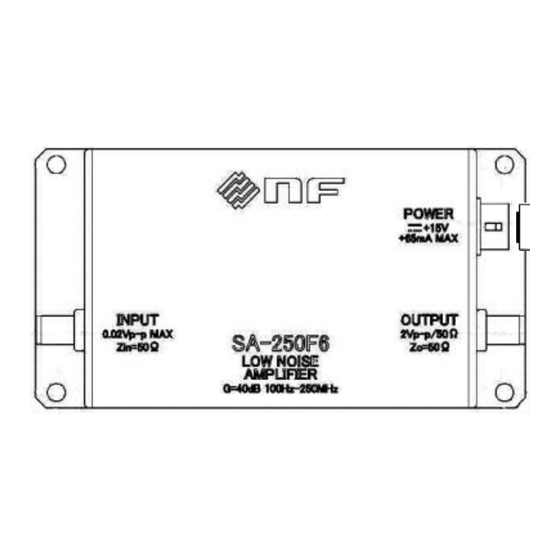
1.1 Overview Overview The SA-250 series are low-noise AC amplifiers with a noise figure of 0.9 dB or less. The voltage gain is 40 dB and the maximum frequency band is 500 MHz, achieving high gain and wideband characteristics. By applying negative feedback technology, this product, which has both input matching of 50 Ω... -
Page 13: Applications
1.3 Applications Applications The SA-250 series are high gain, wideband, and low noise. It is widely used for amplification of small signals. (1) Preamplifier for the magnetic flux measurement by SQUID sensor, etc. (2) Preamplifier for small voltage after voltage conversion of SEM, etc. -
Page 15: Preparation Before Use
2. Preparation before Use Checking before use ....................2-2 Conditions for installation location ................. 2-3 Power supply ......................2-4 2.3.1 Connecting to low noise DC power supply LP series ........2-5 2.3.2 Connecting to DC power supply ..............2-6 SA-250 series... -
Page 16: Checking Before Use
* The bottom plate is attached to the main unit by four plastic screws (M3×6 mm). Optional Item ● Optional items below are separately available. If required, please contact NF or one of our agents. PA-001-2985: SMA SHORT PLUG PA-001-2986: SMA-BNC ADAPTER... -
Page 17: Conditions For Installation Location
Noise may increase, or a malfunction may result. ● For heat dissipation, make sure there is a distance of at least 2 cm between the front panel (the panel on which the model name appears) and surrounding objects. SA-250 series... -
Page 18: Power Supply
We provide the excellent stability and low noise performance DC power supply LP series. For information on those products, please contact the NF corporation or one of our agents. WARNING Do not connect this product to an AC outlet, because doing so is dangerous. -
Page 19: Connecting To Low Noise Dc Power Supply Lp Series
The OUTPUT CABLE A (PA-001-2372) is available to connect this product to LP series power supply. If you require the cable, please contact NF or one of our agents. The following figure shows the connection using the OUTPUT CABLE A. The output of LP series power supply is set as ±15 V. -
Page 20: Connecting To Dc Power Supply
When connecting this product to a stabilized DC power supply, it is convenient to use the PA-001-3018 POWER SUPPLY CABLE that is available for separate purchase. For information on this cable, please contact the NF corporation or one of our agents. The connection diagram for when the PA-001-3018 POWER SUPPLY CABLE is used is illustrated in the following figure. -
Page 21: Panel Features And Basic Operations
3. Panel Features and Basic Operations Panel component names and functions ..............3-2 Input / output connection and installation ............... 3-4 Turning on power and warm-up time ..............3-5 SA-250 series... -
Page 22: Panel Component Names And Functions
(M3) (the length of the screws should be 4 mm or shorter). Note that if the bottom plate is removed, this product and the object to which this product is mounted are electrically connected. The bottom plate is mounted to this product using 6 mm plastic screws (M3). SA-250 series... -
Page 23: Figure 3-1 Front And Rear Panel Views
3.1 Panel component names and functions ④ ④ ③ ② ① ④ ④ ⑤ ⑤ ⑤ ⑤ Figure 3-1 Front and rear panel views. SA-250 series... -
Page 24: Input / Output Connection And Installation
Do not connect this product to an AC outlet, because doing so is dangerous. Attention ・The signal GND and case have the same electric potential. Caution is required when giving a potential to the case or signal GND because doing so may cause electric shock. SA-250 series... -
Page 25: Turning On Power And Warm-Up Time
Turning on power and warm-up time This product exhibits the specified performance immediately after the power is turned on, but if you need highly accurate measurement, allows the device to warm up for at least 10 minutes before use. SA-250 series... -
Page 27: Maintenance
4. Maintenance Before maintenance ....................4-2 Dairy maintenance ....................4-2 Storage, repacking and transportation ..............4-2 Function test ......................4-3 4.4.1 Consumption Current (with No Signal) ............4-4 4.4.2 Operation check ....................4-4 SA-250 series... -
Page 28: Before Maintenance
・ Function test that is necessary for periodical inspection, incoming inspection, or function check after repair If the results of function test are not satisfactory, please contact NF or one of our agents to request calibration or repair. Dairy maintenance ●... -
Page 29: Function Test
・Is the power supply voltage + 15 V within ± 1 V? ・Is the ambient temperature within 18 to 28 °C, and is the ambient humidity within 5 to 85 %RH? ・Is there non-condensation? ・Have 10 minutes or more passed after the power is activated? SA-250 series... -
Page 30: Consumption Current (With No Signal)
DC power supply Output cable A DC power cable 50 Ω BNC T type terminator adapter SMA to BNC Coaxial conversion adapter attenuator 20 dB×2 SMA to BNC conversion adapter Oscilloscope Figure 4-1 Connection diagram for checking operation SA-250 series... -
Page 31: Figure 4-2 Input Voltage Waveforms And Output Voltage Waveforms
4.4 Function test CH-1: CH-1: 100mV/DIV 100mV / DIV CH-2: CH-2: 10V / DIV 100mV/DIV 0.5µs/DIV 0.5ms/dIV Figure 4-2 Input voltage waveforms and output voltage waveforms SA-250 series... -
Page 33: Specifications
4.2 Electrical characteristics .................. 5-2 5.2.1 Input ........................ 5-2 5.2.2 Output ......................5-2 5.2.3 Amplifier ......................5-2 5.2.4 Power supply ....................5-3 5.2.5 General ......................5-3 Notes ........................5-3 External view ......................5-4 5.4.1 SA-250F6 ......................5-4 5.4.2 SA-251F6 ......................5-4 SA-250 series... -
Page 34: Absolute Maximum Ratings
+14 V to +16 V, f = 1 MHz Voltage gain frequency 100 Hz to 1 kHz to Reference frequency of characteristic 250 MHz 500 MHz 1 MHz, Within +0.5 dB / −3.0 dB, Output level 0.5 V SA-250 series... -
Page 35: Power Supply
● Use beyond the absolute maximum ratings and operating temperature range may lead to characteristic deterioration or damage on the internal circuit. ● Static electricity may cause characteristic deterioration or damage. SA-250 series... -
Page 36: External View
Conversion treatment Bottom plate: Plastic Figure 5-1 SA-250F6 external view. 5.4.2 SA-251F6 4×M3 screw Internal insertion length of screw: 4 mm or less Surface treatment Case:Aluminum, non-chromium chemical Conversion treatment Bottom plate: Plastic Figure 5-2 SA-251F6 external view. SA-250 series... -
Page 37: Reference Data
PSRR(Power supply rejection ratio) ............... 6-4 Input VSWR ......................6-4 6.10 Output VSWR ......................6-5 6.11 Output 1 dB gain compression point ..............6-5 6.12 3rd intercept point ....................6-5 6.13 Pulse response ....................... 6-6 6.14 Reverse transmission gain frequency characteristics ..........6-6 SA-250 series... -
Page 38: Reference Data
6.1 Reference data Reference data This chapter shows the reference data of the SA-250 series. The performance of this product may not achieve the level of these data. However, all products have been strictly tested before shipment to check that they meet the specifications. -
Page 39: Voltage Gain Stability (Power Supply Voltage)
Figure 6-3 Voltage gain stability (Power supply voltage) Noise figure Frequency [MHz] Freqency [MHz] (a) SA-250F6 (b) SA-251F6 Figure 6-4 Noise figure Equivalent input voltage noise density 100k 100k Frequency [Hz] Frequency [Hz] (a) SA-250F6 (b) SA-251F6 Figure 6-5 Equivalent input voltage noise density SA-250 series... -
Page 40: Equivalent Input Current Noise Density
Figure 6-6 Equivalent input current noise density PSRR(Power supply rejection ratio) 100k 100k Frequency [Hz] Frequency [Hz] (a) SA-250F6 (b) SA-251F6 Figure 6-7 PSRR Input VSWR 100M 100M Frequency [Hz] Frequency [Hz] (a) SA-250F6 (b) SA-251F6 Figure 6-8 Input VSWR SA-250 series... -
Page 41: Output Vswr
6.11 Output 1 dB gain compression point Frequency [MHz] Frequency [MHz] (a) SA-250F6 (b) SA-251F6 Figure 6-10 1 dB gain compression point 6.12 3rd intercept point Freqency [MHz] Freqency [MHz] (a) SA-250F6 (b) SA-251F6 Figure 6-11 3rd intercept point SA-250 series... -
Page 42: Pulse Response
Figure 6-13 Pulse response (2 Vp-p, 50 MHz square wave output) 6.14 Reverse transmission gain frequency characteristics -100 -100 -110 -110 -120 -120 100M 1000M 100M 1000M Frequency [Hz] Frequency [Hz] (a) SA-250F6 (b) SA-251F6 Figure 6-14 Reverse transmission gain frequency characteristics SA-250 series... -
Page 43: Warranty
For repair service under warranty, the product must be returned to either NF or an agent designated by NF. The Purchaser shall prepay all shipping cost, duties and taxes for the product to NF from another country, and NF shall pay shipping charges to return the product to the purchaser. - Page 44 • We assume no responsibility for influences resulting from the operations in this manual. Copyright 2021, NF Corporation SA-250 series INSTRUCTION MANUAL NF Corporation 6-3-20, Tsunashima Higashi, Kohoku-ku, Yokohama...
- Page 46 NF Corporation 6-3-20, Tsunashima Higashi, Kohoku-ku, Yokohama 223-8508 JAPAN...
Need help?
Do you have a question about the SA-250 Series and is the answer not in the manual?
Questions and answers