Table of Contents
Advertisement
Quick Links
Advertisement
Chapters
Table of Contents

Related Manuals for NF CA5351


Summary of Contents for NF CA5351
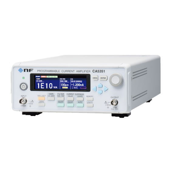
- Page 1 PROGRAMMABLE CURRENT AMPLIFIER CA5351 INSTRUCTION MANUAL NF Corporation...
- Page 3 DA00082422-001 PROGRAMMABLE CURRENT AMPLIFIER CA5351 INSTRUCTION MANUAL...
- Page 5 ――― Preface ――― Thank you for purchasing the “CA5351 PROGRAMMABLE CURRENT AMPLIFIER”. For safe and correct use of this product, please read the “Safety Precautions” section that follows before attempting to use the instrument. Marks and Symbols For safe operation by the user and to prevent damage to the instrument, please give attention to the following marks and symbols that are used in this manual.
- Page 6 The chapters of this manual are described below If you are using this instrument for the first time, begin reading from Chapter1. 1. Introduction This chapter describes a general description of the instrument, including its features, applications, functions, and basic operating principles. 2.
- Page 7 ――― Safety Precautions ――― For safe use of this product, give full attention to the following warnings and cautions. The NF Corporation shall not be held liable for damages that arise from failure to observe these warnings and cautions. This product is a Class I product (with protective conductor terminal) that conforms to the JIS and IEC insulation standards.
- Page 8 Only technicians certified by the NF Corporation are authorized to inspect and touch anything inside the product case. Do not modify this product. Never modify this product in any way. Modification might create new risks. The NF Corporation may refuse to service an instrument that has an unauthorized modification.
- Page 9 Safety Precautions Safety-related symbols The marks and symbols defined below are used in this manual or on the instrument itself to indicate safety information or instructions. Instruction Manual Reference Symbol This symbol notifies the user of a potential hazard and indicates that the user must refer to the instruction manual.
- Page 10 Safety Precautions Disposal of this product To protect the environment, follow the guidelines described below for the disposal of this product. a) Use the services of an industrial waste disposal contractor for disposal of the entire product. b) This product does not use batteries. c) This product does not contain mercury.
- Page 11 Contents Contents Page 1. Introduction ....................1-1 1.1 Features ........................1-2 1.2 Applications ......................1-3 1.3 List of Functions ...................... 1-3 1.4 Operating principles ....................1-4 2. Preparation before use .................. 2-1 2.1 Inspection ........................ 2-2 2.2 Installation ....................... 2-3 2.3 Grounding and power connections ................
- Page 12 Contents 7.2 Daily Maintenance ....................7-2 7.3 Storage, repackaging, and transport ................ 7-3 7.4 Checking the version number .................. 7-3 7.5 Self-diagnostic test ....................7-3 7.6 Performance test ..................... 7-4 7.7 Calibration ....................... 7-7 8. Specifications ....................8-1 8.1 Input section ......................8-2 8.2 Current suppression section ..................
-
Page 13: Table Of Contents
Figures and Tables Figures and Tables Page Figure 1-1 Block diagram of the CA5351 ꞏꞏꞏꞏꞏꞏꞏꞏꞏꞏꞏꞏꞏꞏꞏꞏꞏꞏꞏꞏꞏꞏꞏꞏꞏꞏꞏꞏꞏꞏꞏꞏꞏꞏꞏꞏꞏꞏꞏꞏꞏꞏꞏꞏꞏꞏꞏꞏꞏꞏꞏꞏꞏꞏꞏꞏꞏꞏꞏꞏꞏꞏꞏꞏꞏꞏꞏ 1-5 Figure 2-1 Rack mounting kit assembly diagram (EIA for one unit) ꞏꞏꞏꞏꞏꞏꞏꞏꞏꞏꞏꞏꞏꞏꞏꞏꞏꞏꞏꞏꞏꞏꞏꞏꞏꞏꞏꞏꞏꞏꞏꞏꞏꞏ 2-6 Figure 2-2 Rack mounting kit assembly diagram (EIA for two units) ꞏꞏꞏꞏꞏꞏꞏꞏꞏꞏꞏꞏꞏꞏꞏꞏꞏꞏꞏꞏꞏꞏꞏꞏꞏꞏꞏꞏꞏꞏꞏꞏꞏ 2-6 Figure 2-3 Rack mounting kit assembly diagram (JIS for one unit) ꞏꞏꞏꞏꞏꞏꞏꞏꞏꞏꞏꞏꞏꞏꞏꞏꞏꞏꞏꞏꞏꞏꞏꞏꞏꞏꞏꞏꞏꞏꞏꞏꞏꞏ... - Page 14 Figure 5-23 Status system ꞏꞏꞏꞏꞏꞏꞏꞏꞏꞏꞏꞏꞏꞏꞏꞏꞏꞏꞏꞏꞏꞏꞏꞏꞏꞏꞏꞏꞏꞏꞏꞏꞏꞏꞏꞏꞏꞏꞏꞏꞏꞏꞏꞏꞏꞏꞏꞏꞏꞏꞏꞏꞏꞏꞏꞏꞏꞏꞏꞏꞏꞏꞏꞏꞏꞏꞏꞏꞏꞏꞏꞏꞏꞏꞏꞏꞏꞏꞏꞏꞏꞏꞏꞏ 5-33 Figure 5-24 Standard event status structure ꞏꞏꞏꞏꞏꞏꞏꞏꞏꞏꞏꞏꞏꞏꞏꞏꞏꞏꞏꞏꞏꞏꞏꞏꞏꞏꞏꞏꞏꞏꞏꞏꞏꞏꞏꞏꞏꞏꞏꞏꞏꞏꞏꞏꞏꞏꞏꞏꞏꞏꞏꞏꞏꞏꞏꞏꞏꞏꞏꞏꞏ 5-35 Figure 5-25 Operation status structure ꞏꞏꞏꞏꞏꞏꞏꞏꞏꞏꞏꞏꞏꞏꞏꞏꞏꞏꞏꞏꞏꞏꞏꞏꞏꞏꞏꞏꞏꞏꞏꞏꞏꞏꞏꞏꞏꞏꞏꞏꞏꞏꞏꞏꞏꞏꞏꞏꞏꞏꞏꞏꞏꞏꞏꞏꞏꞏꞏꞏꞏꞏꞏꞏꞏꞏꞏꞏ 5-37 Figure 8-1 External dimensions of the CA5351 ꞏꞏꞏꞏꞏꞏꞏꞏꞏꞏꞏꞏꞏꞏꞏꞏꞏꞏꞏꞏꞏꞏꞏꞏꞏꞏꞏꞏꞏꞏꞏꞏꞏꞏꞏꞏꞏꞏꞏꞏꞏꞏꞏꞏꞏꞏꞏꞏꞏꞏꞏꞏꞏꞏꞏꞏꞏꞏꞏ 8-8 Table 2-1 Packing list ꞏꞏꞏꞏꞏꞏꞏꞏꞏꞏꞏꞏꞏꞏꞏꞏꞏꞏꞏꞏꞏꞏꞏꞏꞏꞏꞏꞏꞏꞏꞏꞏꞏꞏꞏꞏꞏꞏꞏꞏꞏꞏꞏꞏꞏꞏꞏꞏꞏꞏꞏꞏꞏꞏꞏꞏꞏꞏꞏꞏꞏꞏꞏꞏꞏꞏꞏꞏꞏꞏꞏꞏꞏꞏꞏꞏꞏꞏꞏꞏꞏꞏꞏꞏꞏꞏꞏꞏꞏꞏꞏꞏ 2-2 Table 3-1 Initial settings ꞏꞏꞏꞏꞏꞏꞏꞏꞏꞏꞏꞏꞏꞏꞏꞏꞏꞏꞏꞏꞏꞏꞏꞏꞏꞏꞏꞏꞏꞏꞏꞏꞏꞏꞏꞏꞏꞏꞏꞏꞏꞏꞏꞏꞏꞏꞏꞏꞏꞏꞏꞏꞏꞏꞏꞏꞏꞏꞏꞏꞏꞏꞏꞏꞏꞏꞏꞏꞏꞏꞏꞏꞏꞏꞏꞏꞏꞏꞏꞏꞏꞏꞏꞏꞏꞏꞏꞏꞏ 3-6 Table 3-2 I/V Gain Settings and rise time settings of auto filter ꞏꞏꞏꞏꞏꞏꞏꞏꞏꞏꞏꞏꞏꞏꞏꞏꞏꞏꞏꞏꞏꞏꞏꞏꞏꞏꞏꞏꞏꞏꞏꞏꞏꞏꞏꞏꞏ...
- Page 15 1. Introduction 1.1 Features ........................1-2 1.2 Applications ......................1-3 1.3 List of Functions ...................... 1-3 1.4 Operating principles ....................1-4 CA5351...
-
Page 16: Features
1.1 Features Features The “CA5351 PROGRAMMABLE CURRENT AMPLIFIER” is the current input type preamplifier that converts an input current signal from a photo multiplier or a photo diode into a voltage signal. The instrument has both high gain and a wide frequency bandwidth, and gain of the... -
Page 17: Applications
High sensitivity detection of output current signals from photomultipliers or photo diodes Measurement of tiny electrical current signals from electrochemical cells Material research of dielectric substances List of Functions The outline of the functional tree of the CA5351 are shown below. Zero check ON/OFF Input connector FRONT/REAR... -
Page 18: Operating Principles
− Therefore, the gain is the same as the value of the feedback resistor “Rf”. In this section, the block diagram of the CA5351 are presented and the main functions are explained. Zero check (ZERO CHECK) It disconnects the input connection and cuts off an input current. It can be used to check whether there is a current output from a sensor, or an output offset from the CA5351 itself. -
Page 19: Figure 1-1 Block Diagram Of The Ca5351
OUTPUT OVER OVER 1E08 ZERO DETECT DETECT CHECK INPUT 1E07 FRONT 1E06 1E05 POWER SUPPLY ~LINE 1E04 1E03 POWER OUTPUT FRONT CHASSIS ANALOG UNIT ISOLATION GPIB REMOTE PANEL MAIN CPU CONTROL DISPLAY Figure 1-1 Block diagram of the CA5351 CA5351... - Page 20 CA5351...
- Page 21 2.2.2 Installation environment ..................2-3 2.2.3 Rack mounting ....................2-5 2.3 Grounding and power connections ................ 2-10 2.4 Quick operation check ................... 2-13 2.4.1 Display check at power on ................2-13 2.4.2 Self-diagnostic test execution ................. 2-13 2.5 Calibration ......................2-14 CA5351...
-
Page 22: Inspection
2.1 Inspection Inspection Safety check Before using the CA5351, read the “Safety Precautions” section at the beginning of this manual and perform the safety checks described there. Before connecting the instrument to a power supply, read “2.3 Grounding and power connections”... -
Page 23: Installation
Do not cover these air vents. If you notice that the fan is not moving, immediately disconnect the instrument from the power source and contact the NF Corporation or its authorized agent. Continued use of the instrument while the fan is stopped may increase damage to the instrument and make repair difficult. - Page 24 Noise may increase or malfunction may occur. Signal cables should be placed away from the power cords and the other equipment that may produce inductive noise. Failure to do so may result in instrument malfunction or a measurement error. CA5351...
-
Page 25: Figure 2-1 Rack Mounting Kit Assembly Diagram (Eia For One Unit)
2.2 Installation 2.2.3 Rack mounting The CA5351 can be installed in a 19-inch IEC rack, an EIA standard rack or a JIS standard rack by using optional rack mounting kits. The rack mounting kits are available for inch-racks (EIA) and millimeter racks (JIS). - Page 26 When storing the main unit in a rack, do not hold with rack mount adapter alone. Be sure to provide L bracket or shelf on the rack side and hold the main unit. Figure 2-2 Rack mounting kit assembly diagram (EIA for two units) CA5351...
- Page 27 When storing the main unit in a rack, do not hold with rack mount adapter alone. Be sure to provide L bracket or shelf on the rack side and hold the main unit. Figure 2-4 Rack mounting kit assembly diagram (JIS for two units) CA5351...
- Page 28 2.2 Installation Part A detail view Figure 2-5 Rack mounting kit dimensions (EIA for one unit) Part A detail view Figure 2-6 Rack mounting kit dimensions (EIA for two units) CA5351...
- Page 29 2.2 Installation Part A detail view Figure 2-7 Rack mounting kit dimensions (JIS for one unit) Part A detail view Figure 2-8 Rack mounting kit dimensions (JIS for two units) CA5351...
-
Page 30: Figure 2-9 Voltage Selector Switch
The voltage of the switch is set depending on destination. Set the switch to the point where you can hear a clicking sound so that the switch is not in an invalid position. After confirming the voltage of the switch, connect the power cord. 2-10 CA5351... - Page 31 Be sure to conform to the fuse ratings The fuse ratings of the CA5351 are shown below. When power supply voltage is 100 V or 120 V : Time-lag 1 A When power supply voltage is 230 V : Time-lag 0.5 A...
-
Page 32: Figure 2-10 Fuse Replacement
Change the voltage of the switch and replace the fuse after unplugging the power cord from the power inlet of the instrument or a power outlet. WARNING ! There are locations of high-voltage inside this product. Do not remove the cover of this instrument. 2-12 CA5351... -
Page 33: Quick Operation Check
For more detailed check methods → Refer to “7. Maintenance”. 2.4.1 Display check at power on Turn on the power switch of the CA5351 and press the standby switch. After the startup screen is displayed, the main screen will be displayed, and then the instrument will be operational. -
Page 34: Calibration
2.5 Calibration Calibration It is recommended to perform calibration for the CA5351 at least once a year although the appropriate calibration interval depends on how often the instrument is used and the conditions under which it is used. When calibration is necessary, please contact the NF Corporation or its authorized agent. - Page 35 3.6.2 Basic key operation ..................3-17 3.6.3 Simple Operation for the first use ..............3-21 3.7 Basic settings ......................3-22 3.7.1 Zero check ...................... 3-22 3.7.2 Gain settings....................3-23 3.7.3 Filter settings ....................3-23 3.7.4 Current suppression settings ................3-28 CA5351...
-
Page 36: Figure 3-1 Front Panel
3.1 Function and use of each part of the panels Function and use of each part of the panels This section describes the names and functions of each part of the front panel and rear panel of the CA5351. 3.1.1 Front panel Screen... -
Page 37: Figure 3-2 Rear Panel
Spare fuse inside it GPIB connector Air exhaust vent Signal grounding connector Be sure to leave at least 20 mm around so as not to block exhaust. Do not use it as protective ground terminal. Figure 3-2 Rear panel CA5351... -
Page 38: Display At Power "On" And Initial Settings
If settings are lost, the error message will be displayed. However, the instrument will initialize all contents of the configuration memory to the factory default setting, and then it will be operational. Contents of initialization → Refer to “3.2.3 Initial settings” CA5351... -
Page 39: Initial Settings
The behavior when the power is turned on can be set in the “POWER ON STATE” on the “UTILITY” screen. 3.2.3 Initial settings The CA5351 will be initialized to the factory default setting at the following conditions below. When shipped from a factory All of the settings are initial values. - Page 40 ▲ command SCPI, 5350 SCPI × × ▲ <Power on setting> Power on state STBY, STBY&ZERO, Last-STAT&Zero Last-STAT, × × ▲ Last-STAT&ZERO <Configuration memory> contents Initial value × - - - Memory name Initial value × - - - CA5351...
- Page 41 Initial value : Factory default setting *RST : When RESET panel operation or the *RST remote command is executed : Same as left (initial value) ← : With function × : No function ▲ : With function but incompatible with remote control CA5351...
-
Page 42: Figure 3-3 I/O Connectors
INPUT OUTPUT INPUT CHASSIS Figure 3-3 I/O connectors The input and output connectors of the CA5351 are isolated from the enclosure of the instrument with high resistance (10 MΩ). The withstanding voltage is 42 Vpk (DC + ACpeak). ! WARNING... -
Page 43: Figure 3-4 Input Connectors
3.3 I/O connectors Input connectors (INPUT) The input connectors of the CA5351 are located on the front panel and rear panel. Select and use either of them. You cannot use both of them simultaneously. Turning on the “ZERO CHECK” will disconnect the input connector (the selected one) from the internal amplifier. -
Page 44: I/O Connections
Connect and install the instrument as the following methods. Install the CA5351 as close as possible to a sensor or source of a signal, and keep a connection cable to the input connector as short as possible. -
Page 45: Figure 3-7 Connection Of Sensor Without Bias Type
Position the coaxial cables for current input and bias output as parallel as possible and as close as possible. If a loop area formed with the two cables becomes large, electromagnetic induction noise due to external magnetic flux will occur easily. 3-11 CA5351... -
Page 46: Figure 3-9 Example Of Connection Of Photomultiplier
3.4 I/O connections Output voltage of the CA5351 may be saturated when a sensor with large dark current is used as an input signal. The current suppression function can cancel such dark current, thereby larger the “I/V GAIN” can be used. -
Page 47: Figure 3-10 When Signal Source Is Grounded
Because the I/O of the CA5351 are isolated from the enclosure of the instrument, it is less susceptible to effect of a ground loop. However, it is necessary to pay careful attention to grounding of a sensor and the equipment connected to the output of the CA5351. -
Page 48: Operation Tree
3.5 Operation tree Operation tree The operation tree for operating the CA5351 from its panels is presented below. Front panel ZERO CHECK : Zero check ON/OFF LOCAL : Return to the local mode from the remote mode I/V GAIN : Set the I/V gain... - Page 49 : Address settings {LAN} : LAN settings display {IP} : IP address settings {MASK} : Subnet mask settings {GATE} : Default gateway settings {SELFTEST} : Self-diagnosis execution display {POWER-ON STATE} : Settings at power on {INITIALIZE} : Initialization execution display 3-15 CA5351...
-
Page 50: Basic Operation
The calibration information of the instrument was lost and the UNCAL specifications cannot be maintained due to some trouble. Please contact the NF Corporation or its authorized agent as it is malfunction. The instrument is in the remote mode when RMT is displayed. -
Page 51: Basic Key Operation
Turn clockwise to turn up and counterclockwise to turn down Up and down Move the focus up and down and change setting values keys Left and right Move the focus to left and right keys Select a digit 3-17 CA5351... - Page 52 《Focus state》 I / V GAIN I / V GAIN 1E04 1E04 V / A V / A 《Focus state》 《Setting change state》 I / V GAIN I / V GAIN 1E04 1E04 V / A V / A 3-18 CA5351...
- Page 53 “I/V GAIN” value turning the knob or using the (up and down keys). Once the value is changed, it will be reflected immediately. 《Setting change state》 《Setting change state》 I / V GAIN I / V GAIN 1E04 1E05 V / A V / A 3-19 CA5351...
- Page 54 (up and down keys). You can increase the value using (up key) or rotating the knob in clockwise direction, or decrease it using (down key) or rotating the knob in counterclockwise direction. 《Setting change state》 《Setting change state》 VALUE[RANGE] VALUE[RANGE] +0.010 nA +0.000 nA 3-20 CA5351...
-
Page 55: Simple Operation For The First Use
Because the Zero check of the CA5351 is ON, the signal from the sensor is not be inputted to the internal circuit of the CA5351. Therefore, the output voltage is almost 0 V. -
Page 56: Figure 3-12 Input Circuit
Therefore, the input of the CA5351 is turned off while maintaining low load impedance of the sensor. In this state, after the output voltage of the CA5351 is set to 0 V by adjusting the current suppression value and then turn off the Zero check, the offset generated by the instrument can be cancelled. -
Page 57: Gain Settings
3.7 Basic settings 3.7.2 Gain settings Gain of the CA5351 is the conversion gain (I/V GAIN) of the I/V conversion amplifier. The range is from 1E03 (10 ) V/A to 1E10 (10 ) V/A. You can change the value of the gain by pressing the I/V GAIN key or moving the focus to the “I/V GAIN”, and then pressing the ENTER key. - Page 58 Table 3-2 I/V Gain Settings and rise time settings of auto filter I/V Gain Setting Filter rise time (V/A) 1E10 100 µs 1E09 100 µs 1E08 30 µs 1E07 10 µs 1E06 10 µs 1E05 3 µs 1E04 1 µs 1E03 1 µs 3-24 CA5351...
-
Page 59: Figure 3-13 Definition Of Rise Time
+ Figure 3-14 Block diagram of the CA5351 A response of the CA5351 is affected by the rise time decided by the filter as well as response time of the I/V conversion amplifier. When the rise time of the I/V... - Page 60 The longer of the rise time of the I/V conversion amplifier and the rise time of the filter is the close value of the total rise time of the CA5351. Example 1) When the I/V GAIN is 1E10 V/A (rise time ≈ 25 µs) and the filter rise time is 1 µs...
- Page 61 34 kHz 30 µs 11.4 kHz 100 µs 3.4 kHz 300 µs 1.14 kHz 1 ms 340 Hz 3 ms 114 Hz 10 ms 34 Hz 30 ms 11.4 Hz 100 ms 3.4 Hz 300 ms 1.14 Hz 3-27 CA5351...
-
Page 62: Current Suppression Settings
The CA5351 is equipped with a current source for cancelling dark current of a sensor and removing an offset component of the CA5351 itself. If the dark current of the sensor is cancelled, the gain of the CA5351 can be set to larger value, and measurement sensitivity can be improved. - Page 63 An input current fluctuates during the automatic settings and current suppression value goes out of the range In this case, the range and current value will return to the settings before the execution. When the CANCEL key is pressed or the auto current suppression is interrupted 3-29 CA5351...
-
Page 64: Figure 3-15 Block Diagram Of The Current Suppression
Figure 3-15 Block diagram of the current suppression Note that the current suppression function will increase noise in the output signal of the CA5351. The bigger the “I/V GAIN” is or current suppression value is, the greater the degree of noise will increase. - Page 65 4.1.7 POWER ON STATE (Power on state settings screen) ........4-6 4.1.8 INITIALIZE (initialization execution screen) ............4-6 4.2 Memory operation ....................4-7 4.2.1 RECALL (recall) ....................4-8 4.2.2 STORE (save) ....................4-8 4.2.3 CLEAR (clear) ....................4-8 4.2.4 NAME (memory name change) ................. 4-8 CA5351...
-
Page 66: Utilities
You can select parameters by moving the focus on the icon and pressing the ENTER key. INPUT INPUT INPUT INPUT FRONT REAR Restriction The ZERO CHECK key, ON/OFF key in the “FILTER” frame, and ON/OFF and AUTO keys in the “CURRENT SUPPRESS” frame are invalid while the utility screen is being displayed. CA5351... -
Page 67: Reset (Reset Execution Screen)
To change the color, select the color, focus on the “OK” icon and press the ENTER key. After that, the main screen will be displayed. Screen restoration It is difficult to change settings when the backlight is OFF. The screen is restored by pressing the UTILITY key. CA5351... -
Page 68: Information
4.1 Utilities 4.1.4 INFORMATION (product information screen) INFORMATION MODEL CA5351 In the product information screen, the model of the FW Ver. 1.00 instrument, version of the firmware, last adjustment date, ADJ. DATA 2020/09/01 WORK TIME 999,999 hr and total working time are displayed. -
Page 69: Selftest (Self-Diagnostic Test Execution Screen)
If “Fail” message is displayed on the screen, refer to “6.1.2 Errors that occur during panel operations”. MESSAGE MESSAGE No.11 SELFTEST DONE Notes Pass 0x00010000 Voltages will be generated from the output connectors (OUTPUT). It is not recommended to connect a cable to the output connectors. CA5351... -
Page 70: Power On State (Power On State Settings Screen)
This function is utilized for situations when the standby switch cannot be turned off, for instance, in the event the CA5351 is mounted on a rack etc. and the power switch will be turned on and off together with other devices. -
Page 71: Memory Operation
Furthermore, you can back to the main screen from the memory settings screen by pressing the CANCEL key. Restrictions The ZERO CHECK key, ON/OFF key in the “FILTER” frame, ON/OFF key in the “CURRENT SUPPRESS” frame, and AUTO key will be disabled when the memory setting screen is displayed. CA5351... -
Page 72: Recall (Recall)
Resume The CA5351 has the resume function and stores the last operation state. The CA5351 will restore settings to the last them when it is restarted. The resume memory cannot be operated by user. Which setting items can be restored → Refer to “3.2.3 Initial settings”. - Page 73 5.8 Compatibility with commands of the CA5350 ............5-42 5.8.1 Commands table compatible with the CA5350 ..........5-44 5.8.2 Detailed description of the CA5350 commands ..........5-45 5.9 Command execution examples ................5-51 5.9.1 CA5351 commands ..................5-51 5.9.2 CA5350 commands ..................5-51 CA5351...
-
Page 74: Preparations Before Use
5.1.1 Selection of the remote control interface Select one interface among USB, GPIB, or LAN as the remote control interface. The interface connectors are located on the rear panel of the CA5351. It is not possible to use more than one interface at the same time. -
Page 75: Gpib Overview
Restrictions and cautions GPIB-specific functions such as SRQ cannot be used. The CA5351 should be connected directly to the USB connector of the computer by a commercial USB cable. The instrument may not operate correctly if the connection is made via a USB hub. - Page 76 − The length of one cable cannot exceed 4 m Set a different value for the GPIB address of each instrument. If there are instruments that have the same address on a single bus, the instruments may be damaged by output collision. CA5351...
- Page 77 All service request functions are supported. All remote control functions are supported. The parallel poll function is not supported. ALL instrument clear functions are supported Instrument trigger function is not supported. The controller function is not supported. Open collector drive CA5351...
-
Page 78: Lan Overview
(repeater) to be used will be set implicitly. Port number This is the port number that is used when the CA5351 communicates using the TCP protocol. It cannot be changed. It is written in decimal notation. MAC address This indicates an instrument-specific address (physical address). -
Page 79: Communication Cautions
5.1 Preparations before use 5.1.4.3 Connection The CA5351 can distinguish between a straight cable and a crossover cable, so either type of cable can be used. Use the type of cable that is compatible with the connector of the instrument to which the CA5351 is being connected. - Page 80 Receiving LLO (Local Lockout) messages Receiving GET (Group Execute Trigger) messages Receiving REN (Remote Enable) messages Sending a SRQ (Service Request) message Serial polling (receiving SPE or SPD and sending a status byte) Sending an END message (EOI signal as a message terminator) CA5351...
-
Page 81: Switching Between Remote And Local Modes
This operation is not compatible with the USB and LAN interfaces. Remote and local operation with the LAN interface If a command is sent to the CA5351, the instrument will go into the remote mode. Pressing the LOCAL key returns the instrument to the local mode and enables operations from the panel. -
Page 82: Responding To Interface Messages
LOCAL key is disabled. < Go To Local > Move to the local mode The method that is used for sending interface messages from the controller varies with the instrument driver. For details, refer to the manual for each particular driver. 5-10 CA5351... -
Page 83: List Of Commands And Command Tree
List of commands and command tree 5.4.1 List of commands The remote control commands for the CA5351 are listed in the following tables. The descriptions here are in short-form format, which omits all optional keywords. For the long-form formats of commands and parameters, refer to pages listed in the column of “Details”. -
Page 84: Command Tree
Operation status positive transition filter P5-31 - :SYST:ERR? Query error message P5-31 - 5.4.2 Command tree The subsystem command tree for the CA5351 is shown below. The brackets ([ ]) in the tree indicate optional keywords. <Root> Command tree DISPlay BRIGhtness COLor INPut... -
Page 85: Commands
5.5 Commands Commands 5.5.1 Overview The commands of the CA5351 are classified into common commands compliant with IEEE488.2 and subsystem commands corresponding to device-specific functions. 5.5.1.1 Notation For convenience in description, the following notations are used in the manual. < >... -
Page 86: Figure 5-1 Common Command Syntax
5.5 Commands 5.5.1.2 SCPI commands The program messages of the CA5351 consist of common commands and subsystem commands. Here, these command formats and the subsystem command tree are explained. Common commands The common commands are for control of the general instrument functions. -
Page 87: Figure 5-2 Subsystem Command Syntax
This can be used as the short form. This cannot be used, because it does not correspond to INPU either the long form or short form. This cannot be used, because it does not correspond to either the long form or short form. 5-15 CA5351... -
Page 88: Figure 5-3 Numerical Parameter Syntax (
The numerical parameter formats include integer (<NR1>), real number (floating-point) (<NR2>), and real umber (exponent) (<NR3>). <NRf> is a generic expression that includes <NR1>, <NR2>, and <NR3>. The syntax for numerical parameters is illustrated below. <NR1> <NR2> <NR3> Figure 5-3 Numerical parameter syntax (<NRf>) 5-16 CA5351...) -
Page 89: Figure 5-4 Numerical Parameter Syntax (
Figure 5-5 Numerical parameter syntax (<NR2>) Exponent Mantissa Figure 5-6 Numerical parameter syntax (<NR3>) Here, the syntax for the mantissa and the exponent of “Figure 5-6” is illustrated below. Digit Digit Digit − Digit Figure 5-7 Mantissa syntax 5-17 CA5351...) -
Page 90: Figure 5-8 Exponent Syntax
(3) Boolean parameters (<BOL>) The syntax for Boolean parameters is illustrated below. The Boolean parameter value of “0” is interpreted as “false” (OFF) and all the other values are interpreted as “true” (ON). <NBOL> Figure 5-10 Boolean parameter syntax (<BOL>) 5-18 CA5351... -
Page 91: Figure 5-11 Text String Parameters (
The syntax for block parameters is illustrated below. Digit other Byte Digit data than 0 Byte ^END data Figure 5-12 Block parameter syntax (<BLK>) Here, NL is the new line character (ASCII code 10) and ^END is the last byte assertion (EOI). 5-19 CA5351...) -
Page 92: Figure 5-13 Suffix Syntax
The controller can send a combination of two or more common commands and subsystem commands to the instrument in a single program message. The program message syntax is illustrated below. ^END Common command ^END Subsystem command Figure 5-14 Program message syntax Commands are separated by semicolons. 5-20 CA5351... -
Page 93: Figure 5-15 Response Message Syntax
[Response message data] The response message data types are described below. (1) Numerical response data (<NR1>, <NR2>, and <NR3>) The syntax for numerical response data is illustrated below. Digit − Figure 5-16 Integer response data syntax (<NR1>) 5-21 CA5351... -
Page 94: Figure 5-17 Nr2 Numerical Response Data Syntax (
5.5 Commands Digit Digit − Figure 5-17 NR2 numerical response data syntax (<NR2>) Digit Digit Digit − − Figure 5-18 NR3 numerical response data syntax (<NR3>) 5-22 CA5351...) -
Page 95: Figure 5-19 Discrete Response Data Syntax (
Figure 5-20 Numerical Boolean response data syntax (<NBOL>) (4) Text string response data (<STR>) The syntax for text string response data is illustrated below. ” ” ” ” (Character) Character other than “ Figure 5-21 Text string response data syntax (<STR>) 5-23 CA5351...) -
Page 96: Figure 5-22 Defined-Length Arbitrary Block Response Data Syntax (
Figure 5-22 Defined-length arbitrary block response data syntax (<DBLK>) 5.5.2 Sequential commands The commands of the CA5351 are all sequential commands. When execution of the command is completed, the next command will be executed. There are no overlapping commands.) -
Page 97: Command Details
The standard event status register will be cleared when the *ESR? query or the *CLS command is received 5.5.3.4 *IDN? Explanation Query the instrument identification information Response <corporation>, <model>, <serial>, <ver> format <corporation> <STR> Company name (NF Corporation) <model> <STR> Model name (CA5351) <serial> <STR> Serial number <ver> <STR> Version Comments The response is returned without including double quotation marks. - Page 98 Comments • It is SCPI command. “0” is always returned. • Refer to “:SYSTem:TEST” about executing the self-diagnostic test. 5.5.3.12 *WAI Explanation Standby for end of overlapping command execution Comments There are no overlapping commands for the CA5351. 5-26 CA5351...
- Page 99 • When the current value is out of range as a result of changing to a lower range, the value will be set to the maximum or minimum value corresponding to the new range. 5-27 CA5351...
- Page 100 Set and query the current suppression (CS) state Parameters <value> <BOL> Current suppression (CS) state ON | 1 Enable the current suppression (CS) OFF | 0 Disable the current suppression (CS) *RST value: 0 Response <NBOL> format Comments ― 5-28 CA5351...
- Page 101 Set and query the I/V gain value Parameters <value> <NRf> I/V gain value Range: 1 to 8 (1E03, 1E04, 1E05, 1E06, 1E07, 1E08, 1E09, 1E10) Resolution: 1 *RST value: 2 Response <NR1> format Comments The value parameter corresponds to the value in the parentheses. 5-29 CA5351...
- Page 102 Use the rear input connector *RST value: FRON Response FRON | REAR format Comments When the input connector is switched, the Zero check will be enabled. 5.5.3.28 :STATus:OPERation:CONDition? Explanation Query the operation status condition register Response <NR1> format Comments ― 5-30 CA5351...
- Page 103 • If there are more than 16 error messages, the last message in the error queue will be replaced by “Queue overflow” and a new error will not be added until there is a room in the error queue. • The error queue will be cleared when the *CLS command is received. 5-31 CA5351...
- Page 104 • If a command other than a query receives while the execution of the test, the test will be continued but an error will result. • For the self-diagnostic test code, refer to “6.1.2 Errors that occur during panel operations”. 5-32 CA5351...
-
Page 105: Figure 5-23 Status System
5.6 Status system Status system 5.6.1 Status system overview The status system of the CA5351 is illustrated in “Figure 5-23”. Operation status registers Operation condition register Positive/negative Transition filter Standard event registers Standard event status register Operation event register Operation event... -
Page 106: Status Byte
“1”. The message and response message parameters that are set in each register are the sums of all the weights of the bits that have the value of ”1”. 5-34 CA5351... -
Page 107: Figure 5-24 Standard Event Status Structure
Query error & & Always 0 (not used) Operation completed OPC & (Standard event status (Standard event enable register) status register) Standard event Logical OR status summary Status byte ESB (bit 5) Figure 5-24 Standard event status structure 5-35 CA5351... - Page 108 The register will have been cleared to 0 immediately after the power is turned on. The message and response message parameters that are set in each register are the sums of all the weights of the bits that have the value of “1”. 5-36 CA5351...
-
Page 109: Figure 5-25 Operation Status Structure
5.6.4 Operation status The structure of the operation status is illustrated in “Figure 5-25”. The operation conditions register (OPCR) indicates the status of the CA5351 as shown in “Table 5-5”. The transition filter can detect changes in the conditions and generates events. - Page 110 This command can query the operation status event register. The register will be cleared to “0” if it is queried. The register can also be cleared by the *CLS command. The register will have been cleared to “0” immediately after the power is turned on. 5-38 CA5351...
- Page 111 “0” → “1” or “1” → “0” Event register cannot be “0” “0” changed to “1” The message and response message parameters that are set in each register are the sums of all the weights of the bits that have the value of “1”. 5-39 CA5351...
-
Page 112: Error Messages
-221 Settings conflict constraint conflicts among multiple settings. -222 Data out of range The data is outside of the valid range. The parameters are incorrect (inappropriate other Illegal parameter -224 than “Data type error”). value (Example: DISPlay:BRIGhtness %1) 5-40 CA5351... - Page 113 Refer to the explanation for the panel operations that are relevant to each command and query. Errors that occur during normal measurement are also displayed in the same way under remote control operation. 5-41 CA5351...
-
Page 114: Compatibility With Commands Of The Ca5350
†1: It occurs only with the GPIB interface. For the USB interface, SRQ cannot be used. †2: After the response message of the “U1” command is outputted †3: When the “X” command is received 5-42 CA5351... - Page 115 If there is a command or parameter error in any command in the buffer, not only the command with an error, but all commands until the ‘X’ command will be discarded. To execute transferred commands in order, the ‘X’ command should be added to the end of each command. Example: L0XZ0XM0X 5-43 CA5351...
- Page 116 Function Function of the command Compatibility : Available for the CA5351 ▲: Available for the CA5351 but specifications have changed ×: Not available for the CA5351 Details Pages of detaild command description CA5351 command (for reference)
-
Page 117: Detailed Description Of The Ca5350 Commands
• When the CA5351 receives a command, EOI will be ignored irrespective of the settings of the K command. • If the X command hold off is enabled, the CA5351 will hold the bus at the time when the X command is received (without returning NRFD line to H), and the CA5351 will stop receiving the following command. - Page 118 Not used bit2 Not used bit3 Not used bit4 When bit4 is “1”, SRQ will be sent if the CA5351 is ready for receiving commands bit5 When bit5 is “1”, SRQ will be sent if an error occurs. bit6 Not used...
- Page 119 5.8.3.11 T Command Explanation Filter rise time settings Setting 1 µs contents 3 µs 10 µs 30 µs 100 µs 300 µs 1 ms 3 ms 10 ms 30 ms 100 ms 300 ms Default: T. Comments ― 5-47 CA5351...
- Page 120 ±800 uA 000.0 E-06 ±8 mA 0.000 E-03 Query contents of settings CA5351 A0 C1 I0 K0 M000 N0 P0 R03 S0 7 T0 Y0 Z0 <term> (10) (12) (14) (11) (13) (15) Model name CA5351 fixed LCD brightness Zero check state...
- Page 121 5.8 Compatibility with commands of the CA5350 Response Query error state contents CA5351 a b c d e f g h i j k <term> Message terminator, EOI Model name CA5351 fixed The response message is composed of the model name and 10 characters constituted by “1”...
- Page 122 5.8 Compatibility with commands of the CA5350 5.8.3.15 Z Command Explanation Auto filter state settings Setting Disable the auto filter contents Enable the auto filter Default: Z1 Comments ― 5-50 CA5351...
- Page 123 5.9 Command execution examples Command execution examples 5.9.1 CA5351 commands A command execution example using SCPI are shown below. *RST //Initialization *CLS //Status register and error queue initialization :INP:GAIN 4 //Gain = 1E06 ’Change I/V gain :INP:BIAS:CURR:RANG 4 //CS-Range = 8 uA ’Change CS range...
- Page 124 5-52 CA5351...
- Page 125 6.1.1 Errors that occur when the instrument power is turned on ........ 6-3 6.1.2 Errors that occur during panel operations ............6-4 6.1.3 Errors that occur during operation ..............6-5 6.1.4 Errors that occur during remote mode .............. 6-5 6.2 Quick diagnosis ....................... 6-7 CA5351...
-
Page 126: Error Messages
If the instrument requires repair, please contact the NF Corporation or its authorized agent. -
Page 127: Errors That Occur When The Instrument Power Is Turned On
Review the power supply AC line voltage error. detected in the power voltage and the voltage of the supply voltage. voltage selector switch. No.7173 Hardware error The instrument requires repair. No Analog BD response. The analog unit was not detected. CA5351... -
Page 128: Errors That Occur During Panel Operations
If the error occurs †1 repeatedly, the instrument will require repair. Please contact the NF Corporation or its authorized agent. †1: Error codes If an error is detected during self-diagnostic test, it will stop and an error code will be displayed. -
Page 129: Errors That Occur During Operation
Review the power supply AC line voltage error in the power supply voltage. voltage and the voltage of the voltage selector switch. 6.1.4 Errors that occur during remote mode Refer to “5.7 Error messages” when errors occur in the remote mode. CA5351... - Page 130 Excessive signal can be detected at the ・Disconnect the cable from output amplifier and output terminals. the output terminal. OV O ・There is a possibility that voltage is ・Observe the voltage of the applied to the output terminals. output terminal with an oscilloscope. CA5351...
-
Page 131: Quick Diagnosis
If you are still unable to solve the problem or if the method described below fails to restore the instrument to normal functioning, please contact the NF Corporation or its authorized agent. Table 6-5 Troubleshooting... - Page 132 A short circuit of the input Check whether the inner and outer abnormally connection cable conductor of the input cable are not large. short-circuited. An output voltage is being Set the I/V gain to 1E03 and disable saturated. the current suppression. CA5351...
- Page 133 7.4 Checking the version number .................. 7-3 7.5 Self-diagnostic test ....................7-3 7.6 Performance test ..................... 7-4 7.6.1 Introduction ....................... 7-4 7.6.2 Current suppression and gain accuracy ............7-5 7.6.3 Output offset voltage ..................7-6 7.7 Calibration ....................... 7-7 CA5351...
-
Page 134: Maintenance
This instruction manual describes how you can easily check for proper operation of the instrument and test performance. For more advanced inspection, adjustment, calibration, and repair, contact the NF Corporation or its authorized agent. !... -
Page 135: Storage, Repackaging, And Transport
When a problem arises, be sure to include the firmware version number with the description of the problem. Self-diagnostic test Before executing the performance test, execute the self-diagnostic test with reference to “2.4 Quick operation check”. CA5351... -
Page 136: Performance Test
If the performance test indicates that the instrument does not satisfy the specifications, calibration or repair is required. In that case, please contact the NF Corporation or its authorized agent. 1) The test environment The performance test should be performed under the following conditions. -
Page 137: Current Suppression And Gain Accuracy
7.6.2 Current suppression and gain accuracy How to easily measure the total accuracy of the accuracy of the current suppression and the gain accuracy of the amplifier is described below. For more advanced testing, please contact the NF Corporation. CA5351 settings: Zero check is ON. -
Page 138: Output Offset Voltage
7.6 Performance test 7.6.3 Output offset voltage CA5351 settings: Zero check is ON. I/V gain is listed below. The filter function is ON and the rise time is listed below. The current suppression is OFF. Measuring instrument: Set the digital multimeter to DC voltage mode. -
Page 139: Calibration
NF Corporation will adjust or calibrate the instrument to restore performance. If calibration is required, please contact the NF Corporation or its authorized agent. Adjustment or calibration that is performed outside the warranty period is available for a charge. - Page 140 CA5351...
- Page 141 8.2 Current suppression section ..................8-3 8.3 Amplifier section ...................... 8-4 8.4 Output section ......................8-5 8.5 Miscellaneous specifications ..................8-6 8.6 External dimensions ....................8-8 Supplementary value: This value implies supplementary data of this product and it does not guarantee the product performance. CA5351...
-
Page 142: Input Section
100 MΩ or more 1E08 V/A 10 MΩ or more 1E07 V/A 1 MΩ or more 1E06 V/A 100 kΩ or more 1E05 V/A 10 kΩ or more 1E04 V/A 1 kΩ or more 1E03 V/A 100 Ω or more CA5351... -
Page 143: Current Suppression Section
8 µA range to 8 mA range ± (|0.6 % of value| + 0.15 % of range) Auto current suppression This function automatically sets the current suppression range and value to cancel the input current at the time of enabling the auto current suppression. CA5351... -
Page 144: Amplifier Section
Within ±20 % of the setting rise time (10 % to 90 % rise time, supplementary value) Characteristics Low-pass filter (LPF), phase-linear type Attenuation slope 12 dB/oct I/O polarity Inverted (When current flows into the input connector, the output is negative potential.) CA5351... -
Page 145: Output Section
±10 mA (total current of the front and rear connectors) Output impedance 50 Ω (supplementary value) Output offset voltage Within ±30 mV (when I/V gain is 1E10) Within ±20 mV (when I/V gain is 1E04 to 1E09) (Input open and the current suppression OFF) CA5351... -
Page 146: Miscellaneous Specifications
AC 100 V ± 10 %/AC 120 V ± 10 %/AC 230 V +10 % to Voltage −14 %, however 250 V or less Frequency 50 Hz/60 Hz ±2 Hz Power consumption 40 VA or less Overvoltage category Cooling Forced air cooling, rear exhaust CA5351... - Page 147 Approximately 4.5 kg (main unit only, excluding accessories and optional equipment, etc.) RoHS directive Directive 2011/65/EU Safety standards and EMC EMC EN61010-1, EN61010-2-30 EN61326-1 (Group1, ClassA), EN61326-2-1 Note: Applies to products that have a CE marking displayed on the rear panel CA5351...
-
Page 148: Figure 8-1 External Dimensions Of The Ca5351
8.6 External dimensions External dimensions Figure 8-1 External dimensions of the CA5351 CA5351... - Page 149 For repair service under warranty, the product must be returned to either NF or an agent designated by NF. The Purchaser shall prepay all shipping cost, duties and taxes for the product to NF from another country, and NF shall pay shipping charges to return the product to the purchaser.
- Page 150 We assume no responsibility for influences resulting from the operations in this manual. Copyright 2020, NF Corporation CA5351 INSTRUCTION MANUAL NF Corporation 6-3-20, Tsunashima Higashi, Kohoku-ku, Yokohama...
- Page 151 NF Corporation 6-3-20, Tsunashima Higashi, Kohoku-ku, Yokohama 223-8508 JAPAN...
Need help?
Do you have a question about the CA5351 and is the answer not in the manual?
Questions and answers