Table of Contents
Advertisement
Quick Links
Advertisement
Table of Contents

Related Manuals for NF HVA4321


Summary of Contents for NF HVA4321
- Page 1 10kV AC/DC AMPLIFIER HVA4321 INSTRUCTION MANUAL NF Corporation...
- Page 3 DA00012063-001 10kV AC/DC AMPLIFIER HVA4321 Instruction Manual This unit generates high voltage. Incorrect operation may result in death or injury. To prevent death or injury, please read this manual carefully. Keep this manual near the unit so that operators may read at any time.
- Page 5 Describes operation of this product. 5. REPRESENTATIVE CHARACTERISTICS Describes representative characteristic of this product. 6. TROUBLESHOOTING Describes corrective actions when problems occur. 7. MAINTENANCE Describes basic operation tests and daily maintenance procedures. 8. SPECIFICATIONS Lists the specifications (functions and performance). HVA4321...
-
Page 6: Safety Precautions
⎯ Safety Precautions ⎯ To ensure safe use, be sure to observe the following warnings and cautions. NF Corporation shall not be held liable for damages that arise from a failure to observe these warnings and cautions. This product is a Class 1 product (with protective conductor terminal) that conforms to the JIS and IEC insulation standards. - Page 7 This product contains high-voltage parts. Absolutely never remove its cover. Even when the inside of this product needs to be inspected, do not touch the inside. All such inspections are to be performed by service technicians designated by NF Corporation. Do not modify this product.
- Page 8 HVA4321...
-
Page 9: Table Of Contents
Function description and block diagram ............1-3 1.2.1 Function description ....................1-3 1.2.2 Block diagram....................... 1-4 Preparations before use Before using the HVA4321..................2-1 Installation......................2-2 Grounding and power supply connection............2-3 Nomenclature and functions Signal system......................3-1 3.1.1 Internal DC bias signal source..................3-1 3.1.2... - Page 10 When suspecting a fault..................6-1 Maintenance Daily maintenance ....................7-1 Inspection......................7-2 When the unit is not used for a long time ............7-2 Performance test....................7-3 7.4.1 Test of constant voltage mode..................7-3 7.4.2 Test of constant current mode ..................7-4 HVA4321...
- Page 11 Amplifier ........................ 8-2 8.2.1 Characteristics of constant voltage mode ..............8-2 8.2.2 Characteristics of constant current mode..............8-4 Output area......................8-5 Monitor output ...................... 8-5 Other input/output signal ..................8-6 Protection circuit ....................8-7 Others ........................8-7 General items ......................8-8 HVA4321...
- Page 12 Figures Page Figure1-1. HVA4321 Block diagram....................1-4 Figure2-1. Check of power OFF ...................... 2-3 Figure2-2. Check of internal high voltage DC power OFF ............. 2-3 Figure2-3. Inserting power cable connector................... 2-4 Figure2-4. Using conversion connector ..................2-4 Figure2-5. Casing ground terminal ....................2-5 Figure3-1.
- Page 13 Figure4-49. Using external DC bias signal ..................4-38 Figure4-50. Constant current constant voltage mode (total mode)..........4-41 Figure4-51. Constant current constant voltage mode (load mode) ..........4-41 Figure4-52. Internal high voltage DC power OFF ................4-42 Figure4-53. Switch settings......................4-42 HVA4321...
- Page 14 How to remove fan cover ....................7-1 Figure7-2. Check method of constant voltage mode ..............7-3 Figure7-3. Check method of constant current mode..............7-4 Figure8-1. Output current ........................ 8-2 Figure8-2. Voltage and current range allowed for output .............. 8-3 HVA4321...
- Page 15 Tables Page Table2-1. Accessories........................2-3 Table3-1. Logic of HIGH VOLTAGE POWER SUPPLY ON/OFF............3-3 Table3-2. Logic of signal system ON/OFF signal ................. 3-3 Table3-3. Logic of SIGNAL ON/OFF signal..................3-3 Table3-4. Status contact output signal ..................3-3 HVA4321...
- Page 16 Figures HVA4321...
-
Page 17: Overview
1. Overview Features ・・・・・・・・・・・・・・・・・・・・・・・・・・・・・・・・・・・・・・・・・ Function description and block diagram ・・・・・・・・・・・・・・ 1.2.1 Function description ・・・・・・・・・・・・・・・・・・・・・・・・・・・ 1.2.2 Block diagram ・・・・・・・・・・・・・・・・・・・・・・・・・・・・・・・・... - Page 18 HVA4321...
-
Page 19: Features
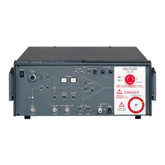
1.1 Features Features The HVA4321 10 kV AC/DC amplifier is a constant voltage/constant current amplifier capable of ±10 kVpk and ±10 mApk. Since the unit has a DC bias signal source, it can be used as a DC power supply that is individually capable of high voltage output. - Page 20 Visual display of high voltage output During high voltage output, the LED around the output connector lights and the revolution changes depending on the output voltage level. Remote control is capable. Signals can be turned ON/OFF with an external control signal. HVA4321...
-
Page 21: Function Description And Block Diagram
The unit is using ±12 kV power supply to obtain the output of 10 kVpk. This power supply can be individually turned ON/OFF for safety. External control system The signal source can be turned ON/OFF with an external contact signal or TTL level signal. HVA4321... - Page 22 1.2 Function description and block diagram HVA4321...
-
Page 23: Preparations Before Use
2. Preparations before use Before using the HVA4321 ・・・・・・・・・・・・・・・・・・・・・・・・・ Installation ・・・・・・・・・・・・・・・・・・・・・・・・・・・・・・・・・・・・・・・ Grounding and power supply connection ・・・・・・・・・・・・・... -
Page 25: Before Using The Hva4321
2.1 Before using the HVA4321 Before using the HVA4321 Safety check Before using the HVA4321, read the following items in the instruction manual: [INSTRUCTIONS FOR SAFE USE] (Described at the beginning of this instruction manual.) [2.3 Grounding and connection of power supply]... -
Page 26: Installation
Do not put an object on the unit. WARNING ! Do not use a radio transmitter or a cell phone around this unit. Unintended high voltage output may be given due to radio. HVA4321... -
Page 27: Grounding And Power Supply Connection
Make sure that the HIGH VOLTAGE POWER SUPPLY switch on the front panel is pressed. H I GH VO LTAGE POW ER SUPPLY PUSH OFF O FF PU LL ON This must be pressed. 押し 込まれている状態 Figure2-2. Check of internal high voltage DC power OFF HVA4321... -
Page 28: Figure2-3. Inserting Power Cable Connector
The casing of the unit is then grounded. Using 3-pin 2-pin adapter When 3-pin 2-pin conversion adapter is sued, be sure to connect the ground wire of the conversion adapter to the ground terminal near the outlet. Ground 3-pin 2-pin adapter Figure2-4. Using conversion connector HVA4321... -
Page 29: Figure2-5. Casing Ground Terminal
When a fuse is replaced, be sure to disconnect the power cable from the outlet. Replace it with the same standard one. For this product, the time lag type fuse with the rating of 10A/250V and φ2 x 20 mm is used. HVA4321... - Page 30 2.3 Grounding and power supply connection HVA4321...
-
Page 31: Nomenclature And Functions
3. Nomenclature and functions Signal system ・・・・・・・・・・・・・・・・・・・・・・・・・・・・・・・・・・・・ 3.1.1 Internal DC bias signal source ・・・・・・・・・・・・・・・・・・ 3.1.2 External bias signal input ・・・・・・・・・・・・・・・・・・・・・・ 3.1.3 External signal input ・・・・・・・・・・・・・・・・・・・・・・・・・・・ 3.1.4 Input signal ON/OFF ・・・・・・・・・・・・・・・・・・・・・・・・・・ Amplifier ・・・・・・・・・・・・・・・・・・・・・・・・・・・・・・・・・・・・・・・・・ 3.2.1 Amplifier operation mode ・・・・・・・・・・・・・・・・・・・・・・ 3.2.2 Amplifier control ・・・・・・・・・・・・・・・・・・・・・・・・・・・・・・... -
Page 33: Signal System
OSC input. ON/OFF Valid or invalid external DC bias signal is set. ± 10V M AX Z i n 10k Ω When it is ON, the external DC bias signal input is valid. Figure3-2. External DC bias input HVA4321... -
Page 34: External Signal Input
S I GNAL Input to the amplifier area for INT DC BIAS, EXT O FF DC BIAS and OSC INPUT is switched ON/OFF. When it is ON, each input signal is given to the high voltage amplifier. Figure3-4. Signal ON/OFF switch HVA4321... - Page 35 ・Temperature in the casing became high. ・Voltage of the internal control power supply became low. ・When the LIMIT/TRIP is set to TRIP, the current limiter circuit was activated. In the cases above, SIGNAL ON cannot be recovered unless the cause is removed. HVA4321...
-
Page 36: Amplifier
Then, constant DC bias can be applied to the capacity load. In constant voltage mode, this function is invalid for either setting. OVER LOAD 1kV / 1V DC B I AS 1m A / 1V Figure3-5. Operation mode switch HVA4321... - Page 37 Approx. 50 Hz or more ・For 1000 pF Approx. 5 Hz or more OVERLOAD It is the LED that lights if the unit amplifier has a fault. It lights if the unit is overloaded or the limiter is activated. HVA4321...
-
Page 38: Amplifier Control
-6kV で制限される。 Figure3-7. Operation of voltage limiter (1) Input voltage 入 力 電 圧 Limiter level リ ミ ッ タ レ ベ ル Output voltage 出 力 電 圧 Exceeding limiter level リミッタレベルを越える。 Figure3-8. Operation of voltage limiter (2) HVA4321... -
Page 39: Figure3-9. Operation Of Current Limiter
・The voltage waveform of a load capacity may be non-linear due to limitation by average current, resulting in increase of peak current. LIMIT/TRIP In LIMIT, the output current is limited with the setting value. In TRIP, if the output current exceeds the set value, SIGNAL is switched OFF and the output is 0V. HVA4321... -
Page 40: Figure3-10. Response Function In Constant Voltage Mode
Response rightmost Response leftmost Figure3-11. Response function in constant current mode CAUTION ! The step response using RESPONSE may not be sufficiently adjusted depending on setting conditions or load conditions. In a case, oscillation may occur. HVA4321... -
Page 41: Output
ON/OFF status of this switch. If this switch is ON, turn it OFF once and turn it ON again. Power switch ON again HIGH VOLTAGE POWER SUPPLY switch Internal high voltage power supply ON now Not ON Figure3-13. Power supply and internal high voltage DC power HVA4321... -
Page 42: Figure3-14. Return Terminal
1m A / 1V CURRENT SELECT LOAD TO TAL OUTPUT Lo LOAD TOTAL MON I TOR CURRENT CURRENT VO LTAGE CURRENT 1V / 1kV 1V / 10m A Zou t 50 Ω Zou t 50 Ω Figure3-14. Return terminal HVA4321 3-10... -
Page 43: Monitor And Control Signal System
ス イ ッ チ O FF O FF SIGNAL SWITCH SIGNAL ON/OFF S I G N A L O N / O FF H I G H H I G H STATUS STA TU S Figure3-16. Status signal output HVA4321 3-11... -
Page 44: Control Signal System
TTL (Lo : ON ) TTL (Lo : ON ) OSCI NPUT ON / O FF EXT DC B I ASON / O FF TTL (Lo : ON ) TTL (Lo : ON ) Figure3-18. Remote control input HVA4321 3-12... -
Page 45: Figure3-19. Remote Control Input Circuit
Therefore, when external control is not used, be sure to short-circuit the control input terminal at the back with an accompanying shorting plug. If shorting is not performed, the internal high voltage DC power supply is not ON although HIGH VOLTAGE POWER SUPPLY ON/OFF switch on the panel is "ON". HVA4321 3-13... -
Page 46: Figure3-20. Remote Control Of High Voltage Power Supply On/Off
Signal output Figure3-21. Remote control of signal system ON/OFF Table3-2. Logic of signal system ON/OFF signal ON/OFF signal of signal system in remote control operation High(Approx. 5V) Low(Approx. 0V) Back panel control signal Contact Open Close Signal status HVA4321 3-14... -
Page 47: Figure3-22. Remote Control Of Signal On/Off
過 電流 など で出 力 がオ フす る と、 Figure3-22. Remote control of signal ON/OFF Table3-3. Logic of SIGNAL ON/OFF signal SIGNAL ON/OFF signal in remote control operation High(Positive logic) Low(Positive logic) Back panel control signal Contact Open Close Signal status HVA4321 3-15... -
Page 48: Figure3-23. Example Of Status Contact Output
S I G NA L O N に 点 灯 す る 表 示 灯 な ど (Activated with AC100V) AC 250V 3A M AX DC 30V 3A M AX To AC100V A C 1000V へ Figure3-23. Example of status contact output HVA4321 3-16... -
Page 49: Power Supply Items
When a fuse is replaced, be sure to disconnect the power cable from the outlet. Replace it with the same standard one. For this product, the time lag type fuse with the rating of 10A/250V and φ2 x 20 mm is used. HVA4321 3-17... -
Page 51: Front Panel
Gives signal that indicates (3.2.1) 直流バイアスを外部から入力する SIGNALのオンオフ状態を示す信号を output voltage monitor. 負荷に流れる電流を制御します。 controlled ignoring the leak current to stray external DC bias input. SIGNAL ON/OFF status. BNC接栓です。 BN C 接栓です。 出力します (3.3.1) (3.2.3) capacitance. (3.1.2) (3.3.2) (3.3.1) (3.1.2) (3.3.2) (3.2.3) HVA4321 3-18... -
Page 53: Rear Panel
DC bias signal for remote Be sure to connect the accompanying control operation. (3.3.2) 安全のため必ず附属の3pin電源コードで接地付き 3 pin power cable to the outlet with オン・オフ制御信号を入力します。 (3.3.2) オン・オフ制御信号を入力します。 control operation. (3.3.2) (3.3.2) コンセントに接続してください。 ground for safety. (3.3.2) (3.3.2) (3.4) (3.4) HVA4321 3-19... -
Page 55: Operation Method
4. Operation method Operation example in constant voltage mode ・・・・・・・・・ 4.1.1 Panel setting ・・・・・・・・・・・・・・・・・・・・・・・・・・・・・・・・・ 4.1.2 Connection of signal source and connection of load ・・・・・・・・・・・・・・・・・・・・・・・・・・・・ 4.1.3 Power supply and internal high voltage DC power supply ・・・・・・・・・・・・・・・・・・・・・・・・・・・・・ 4.1.4 Signal output and adjustment ・・・・・・・・・・・・・・・・・・... -
Page 57: Operation Example In Constant Voltage Mode
DC is detected here. The monitor is hardly affected.) CAUTION ! Effect of stray capacitance of the cable is found only for AC signal output. Effect of stray signal is not found for DC signal. Therefore, use the DC signal in total mode. HVA4321... -
Page 58: Figure4-2. Constant Voltage Mode (Load Mode)
・ One end of load cannot be directly grounded. There is a current detection resistance (33Ω) between load end and ground. ・The voltage of output current x current detection resistance (33Ω) for set output voltage is an error in load. (When the load current is 10 mA, the error is 330 mV.) HVA4321... -
Page 59: Panel Setting
Turn the internal DC bias knob to the leftmost position to minimize the value. Turn OFF the switches of DC BIAS, OSC INPUT and EXT DC BIAS INPUT. DC B I AS O FF NORM AL I NVERT GA I N Figure4-4. Switch settings HVA4321... -
Page 60: Figure4-5. Output Mode Settings
VO LTAGE CURRENT OUTPUT ± 10V M AX TTL (Lo : ON ) 1V / 1kV 1V / 1m A Z i n 10k Ω Zou t 10k Ω Zou t 50 Ω Zou t 50 Ω Figure4-6. Local settings HVA4321... -
Page 61: Figure4-7. Limiter Settings
0V. Select either one as required. f) Current monitor mode settings In total mode, set it to TOTAL CURRENT and in load mode, set it to LOAD CURRENT. CURRENT SELECT LOAD TO TAL Figure4-8. Current monitor mode settings HVA4321... -
Page 62: Connection Of Signal Source And Connection Of Load
EXT DC B I AS 信号発生器 I NPUT OUTPUT ± 10V M AX ± 10V M AX Z i n 10k Ω Z i n 10k Ω DC standard power supply 直流基準電源 Figure4-10. Connection of external signal source signal HVA4321... -
Page 63: Figure4-11. Connection Of Monitor
Tighten it securely OUTPUT H i Accompanying high 締めてく ださ い。 voltage cable 附属の高圧ケーブル OUTPUT Lo LOAD TO TAL CURRENT CURRENT ± 10kV MAX ± 10m A M AX Accompanying return cable 附属のリ タ ーンケーブル Figure4-12. Connection of output cable HVA4321... - Page 64 Tighten the binding post terminal of OUTPUT Lo securely. If it is loose, electric shock may occur when touching the load grounding or the return cable. Check sometimes if it is not loose when the power is OFF and it is safe. HVA4321...
-
Page 65: Power Supply And Internal High Voltage Dc Power Supply
When the power is supplied, the internal high voltage DC power supply is always OFF regardless of ON/OFF status of the HIGH VOLTAGE POWER SUPPLY switch. If this switch is ON, turn OFF once and turn it ON again. HVA4321... -
Page 66: Figure4-14. Internal High Voltage Dc Power On
4) Are all fans at the back operating? Action Check if there is any object that blocks rotation of a fan. If a fan does not rotate without any blocking, the fan may be faulty. It must be repaired. HVA4321 4-10... -
Page 67: Signal Output And Adjustment
If fine adjustment of the output level is required, adjust it at the oscillator or adjust it with GAIN of the unit. Turn GAIN to the left, the gain is decreased. Turn GAIN to the right, the gain is increased. The gain can be adjusted in the range of approximately ±3%. HVA4321 4-11... -
Page 68: Figure4-16. Using External Oscillator
The gain of 1 kHz band or more may vary depending on the RESPONSE knob position. Refer to "5.2 Characteristics in constant voltage mode, Chapter 5". When the frequency is used at 1 kHz or more, measure the output voltage of the voltage monitor and adjust RESPONSE so that the desired amplitude may be obtained. HVA4321 4-12... -
Page 69: Signal Off
Internal high voltage DC power supply OFF When the HIGH VOLTAGE POWER SUPPLY switch is turned OFF, the output of the internal high voltage DC power supply is 0V and the amplifier cannot give high voltage output. HVA4321 4-13... -
Page 70: Operation Example In Constant Current Mode (Total)
In constant current mode, DC cannot be run for capacity load. At this time, the output for DC signal is the same as that in open status. When SIGNAL is ON, maximum ±12 kV output is given to the OUTPUT Hi terminal. Never apply DC to capacity load in constant current mode. HVA4321 4-14... -
Page 71: Figure4-18. Total Mode
CT. Total output of leak current lstr with wire capacity and load current lload is given to the current monitor. (Leak current lint (AC) with stray capacity in the amplifier runs through the current detection resistance, but only DC is detected here. The monitor is hardly affected.) HVA4321 4-15... -
Page 72: Panel Setting
Turn the internal DC bias knob to the leftmost position to minimize the value. Turn OFF the switches of DC BIAS, OSC INPUT and EXT DC BIAS INPUT. DC B I AS O FF NORM AL I NVERT GA I N O FF Figure4-20. Switch settings HVA4321 4-16... -
Page 73: Figure4-21. Output Mode Settings
CURRENT OUTPUT ± 10V M AX TTL (Lo : ON ) 1V / 1kV 1V / 1m A Z i n 10k Ω Zou t 10k Ω Zou t 50 Ω Zou t 50 Ω Figure4-22. Local settings HVA4321 4-17... -
Page 74: Figure4-23. Limiter Settings
0V. Select either one as required. f) Current monitor mode settings In total mode of constant current mode, set it to TOTAL CURRENT CURRENT SELECT LOAD TO TAL Figure4-24. Current monitor mode settings HVA4321 4-18... -
Page 75: Connection Of Signal Source And Connection Of Load
EXT DC B I AS 信号発生器 I NPUT OUTPUT ± 10V M AX ± 10V M AX Z i n 10k Ω Z i n 10k Ω DC standard power supply 直流基準電源 Figure4-26. Connection of external signal source signal HVA4321 4-19... -
Page 76: Figure4-27. Connection Of Monitor
OUTPUT H i Accompanying high 締めてく ださ い。 voltage cable 附属の高圧ケーブル OUTPUT Lo LOAD TO TAL CURRENT CURRENT ± 10kV M AX ± 10m A M AX Accompanying return cable 附属のリ タ ーンケーブル Figure4-28. Connection of output cable HVA4321 4-20... - Page 77 Tighten the binding post terminal of OUTPUT Lo securely. If it is loose, electric shock may occur when touching the load grounding or the return cable. Check sometimes if it is not loose when it is safe with the power OFF. HVA4321 4-21...
-
Page 78: Power Supply And Internal High Voltage Dc Power Supply
When the power is supplied, the internal high voltage DC power supply is always OFF regardless of ON/OFF status of the HIGH VOLTAGE POWER SUPPLY switch. If this switch is ON, turn OFF once and turn it ON again. HVA4321 4-22... -
Page 79: Figure4-30. Internal High Voltage Dc Power On
4) Are all fans at the back operating? Action Check if there is any object that blocks rotation of a fan. If a fan does not rotate without any blocking, the fan may be faulty. It must be repaired. HVA4321 4-23... -
Page 80: Signal Output And Adjustment
If fine adjustment of the output level is required, adjust it at the oscillator or adjust it with GAIN of the unit. Turn GAIN to the left, the gain is decreased. Turn GAIN to the right, the gain is increased. The gain can be adjusted in the range of approximately ±3%. HVA4321 4-24... -
Page 81: Figure4-32. Using External Oscillator
The gain of 200 kHz band or more may vary depending on the RESPONSE knob position. Refer to "5.3 Characteristics in constant voltage mode, Chapter 5". When the frequency is used at 200 Hz or more, measure the output voltage of the voltage monitor and adjust RESPONSE so that the desired amplitude may be obtained. HVA4321 4-25... -
Page 82: Signal Off
Internal high voltage DC power supply OFF When the HIGH VOLTAGE POWER SUPPLY switch is turned OFF, the output of the internal high voltage DC power supply is 0V and the amplifier cannot give high voltage output. HVA4321 4-26... -
Page 83: Operation Example In Constant Current Mode (Load)
In constant current mode, DC cannot be run for capacity load. At this time, the output for DC signal is the same as that in open status. When SIGNAL is ON, maximum ±12 kV output is given to the OUTPUT Hi terminal. Never apply DC to capacity load in constant current mode. HVA4321 4-27... -
Page 84: Figure4-34. Load Mode
= lload + lstr CAUTION ! Current lout from the output terminal cannot exceed the maximum current of this unit. In load mode, load current is directly detected. Only load current can be monitored with the current monitor. HVA4321 4-28... -
Page 85: Panel Setting
Turn the internal DC bias knob to the leftmost position to minimize the value. Turn OFF the switches of DC BIAS, OSC INPUT and EXT DC BIAS INPUT. DC B I AS O FF NORM AL I NVERT GA I N O FF Figure4-36. Switch settings HVA4321 4-29... -
Page 86: Figure4-37. Output Mode Settings
CURRENT OUTPUT ± 10V M AX TTL (Lo : ON ) 1V / 1kV 1V / 1m A Z i n 10k Ω Zou t 10k Ω Zou t 50 Ω Zou t 50 Ω Figure4-38. Local settings HVA4321 4-30... -
Page 87: Figure4-39. Limiter Settings
0V. Select either one as required. f) Current monitor mode settings In load mode of constant current mode, set it to LOAD CURRENT. CURRENT SELECT LOAD TO TAL Figure4-40. Current monitor mode settings HVA4321 4-31... -
Page 88: Connection Of Signal Source And Connection Of Load
EXT DC B I AS I NPUT 信号発生器 OUTPUT ± 10V M AX ± 10V M AX Z i n 10k Ω Z i n 10k Ω DC standard power supply 直流基準電源 Figure4-42. Connection of external signal source signal HVA4321 4-32... -
Page 89: Figure4-43. Connection Of Monitor
LOAD TO TAL CURRENT CURRENT ± 10kV MAX ± 10mA M AX Stray 浮遊 容 量 capacitance Ground plane, etc. グ ラン ド プレ ー ンな ど Accompanying return cable 附属のリ タ ーンケーブル Figure4-44. Connection of output cable HVA4321 4-33... - Page 90 Tighten the binding post terminal of OUTPUT Lo securely. If it is loose, electric shock may occur when touching the load grounding or the return cable. Check sometimes if it is not loose when it is safe with the power OFF. HVA4321 4-34...
-
Page 91: Power Supply And Internal High Voltage Dc Power Supply
When the power is supplied, the internal high voltage DC power supply is always OFF regardless of ON/OFF status of the HIGH VOLTAGE POWER SUPPLY switch. If this switch is ON, turn OFF once and turn it ON again. HVA4321 4-35... -
Page 92: Figure4-46. Internal High Voltage Dc Power On
4) Are all fans at the back operating? Action Check if there is any object that blocks rotation of a fan. If a fan does not rotate without any blocking, the fan may be faulty. It must be repaired. HVA4321 4-36... -
Page 93: Signal Output And Adjustment
If fine adjustment of the output level is required, adjust it at the oscillator or adjust it with GAIN of the unit. Turn GAIN to the left, the gain is decreased. Turn GAIN to the right, the gain is increased. The gain can be adjusted in the range of approximately ±3%. HVA4321 4-37... -
Page 94: Figure4-48. Using External Oscillator
The gain of the 200 Hz band or more may vary depending on the RESPONSE knob position. Refer to "5.3 Characteristics in constant voltage mode, Chapter 5". When the frequency is used at 200 Hz or more, measure the output voltage of the voltage monitor and adjust RESPONSE so that the desired amplitude may be obtained. HVA4321 4-38... -
Page 95: Signal Off
Internal high voltage DC power supply OFF When the HIGH VOLTAGE POWER SUPPLY switch is turned OFF, the output of the internal high voltage DC power supply is 0V and the amplifier cannot give high voltage output. HVA4321 4-39... -
Page 96: Operation Example In Constant Current + Constant Voltage Mode
Constant current operation is available for AC signal and constant voltage operation is available for DC signal. When the signal is ON, unusual voltage output is not given with the output open. When the output is short-circuited, be careful for DC short-circuit current. HVA4321 4-40... -
Page 97: Figure4-50. Constant Current Constant Voltage Mode (Total Mode)
In constant current + constant voltage mode, the current detection circuit detects AC components and the voltage detection circuit detects DC components for independent control. Total mode and load mode can be used same as normal constant current mode. HVA4321 4-41... -
Page 98: Panel Setting
Turn the internal DC bias knob to the leftmost position to minimize the value. Turn OFF the switches of DC BIAS, OSC INPUT and EXT DC BIAS INPUT. DC B I AS O FF NORM AL I NVERT GA I N Figure4-53. Switch settings HVA4321 4-42... -
Page 99: Figure4-54. Output Mode Settings
CURRENT OUTPUT ± 10V M AX TTL (Lo : ON ) 1V / 1kV 1V / 1m A Z i n 10k Ω Zou t 10k Ω Zou t 50 Ω Zou t 50 Ω Figure4-55. Local settings HVA4321 4-43... -
Page 100: Figure4-56. Limiter Settings
0V. Select either one as required. f) Current monitor mode settings In total mode, set it to TOTAL CURRENT. In load mode, set it to LOAD CURRENT. CURRENT SELECT LOAD TO TAL Figure4-57. Current monitor mode settings HVA4321 4-44... -
Page 101: Connection Of Signal Source And Connection Of Load
EXT DC B I AS I NPUT 信号発生器 OUTPUT ± 10V M AX ± 10V M AX Z i n 10k Ω Z i n 10k Ω DC standard power supply 直流基準電源 Figure4-59. Connection of external signal source signal HVA4321 4-45... -
Page 102: Figure4-60. Connection Of Monitor
Connect a measuring instrument such as oscilloscope or voltmeter to VOLTAGE MONITOR or CURRENT MONITOR as required. OUTPUT Lo S I GNAL ON / O FF STATUS MON I TOR LOAD TO TAL OUTPUT VO LTAGE CURRENT CURRENT CURRENT Oscilloscope オシロスコ ープ Voltmeter 電圧計 Figure4-60. Connection of monitor HVA4321 4-46... -
Page 103: Figure4-61. Connection Of Output Cable
Tighten the binding post terminal of OUTPUT Lo securely. If it is loose, electric shock may occur when touching the load grounding or the return cable. Check sometimes if it is not loose when it is safe with the power OFF. HVA4321 4-47... -
Page 104: Power Supply And Internal High Voltage Dc Power Supply
When the power is supplied, the internal high voltage DC power supply is always OFF regardless of ON/OFF status of the HIGH VOLTAGE POWER SUPPLY switch. If this switch is ON, turn OFF once and turn it ON again. HVA4321 4-48... -
Page 105: Figure4-63. Internal High Voltage Dc Power On
4) Are all fans at the back operating? Action Check if there is any object that blocks rotation of a fan. If a fan does not rotate without any blocking, the fan may be faulty. It must be repaired. HVA4321 4-49... -
Page 106: Signal Output And Adjustment
If fine adjustment of the output level is required, adjust it at the oscillator or adjust it with GAIN of the unit. Turn GAIN to the left, the gain is decreased. Turn GAIN to the right, the gain is increased. The gain can be adjusted in the range of approximately ±3%. HVA4321 4-50... -
Page 107: Figure4-65. Using External Oscillator
The gain in the AC range may vary depending on the RESPONSE knob position. Refer to "5.4 Characteristics of constant current + constant voltage mode, Chapter 5". When the frequency is used at specific frequency, measure the output voltage of the voltage monitor and adjust RESPONSE so that the desired amplitude may be obtained. HVA4321 4-51... -
Page 108: Signal Off
Internal high voltage DC power supply OFF When the HIGH VOLTAGE POWER SUPPLY switch is turned OFF, the output of the internal high voltage DC power supply is 0V and the amplifier cannot give high voltage output. HVA4321 4-52... -
Page 109: Change Of Load And Power Off
PUSH O FF O FF PU LL ON 危険防止のた め、 出力の配線を 変更する と き は必ず 上のス イ ッ チ を 押し て H V 電源を OF F し て く だ さ い。 Figure4-68. Internal high voltage power supply OFF HVA4321 4-53... -
Page 110: Figure4-69. Checking Items Before Power Off
1V / 1m A Zou t 50 Ω Zou t 50 Ω Figure4-69. Checking items before power OFF After checking items above, turn OFF the POWER. POW ER DC B I AS Turn OFF オフ にし ます。 Figure4-70. POWER OFF HVA4321 4-54... -
Page 111: Figure4-71. Removing High Voltage Cable
安 全の た め 抜 い てく だ さ い 。 Figure4-71. Removing high voltage cable After change of the load, be sure to insert the high voltage cable into the connector. e) Re-supply Make sure again that connections are safe. Turn ON the POWER. HVA4321 4-55... -
Page 112: Power Supply Off
Do not turn OFF the POWER switch with HIGH VOLTAGE POWER SUPPLY ON. Approximately 200V output may be generated. Be sure to turn OFF HIGH VOLTAGE POWER SUPPLY first before POWER OFF. However, this does not apply to emergency. Turn OFF the POWER immediately. HVA4321 4-56... -
Page 113: Remote Control
OSCI NPUT ON / O FF EXT DC B I ASON / O FF Switch ス イ ッチ Computer コ ンピ ュ ー タ TTL (Lo : ON ) TTL (Lo : ON ) Contact signal 接 点 信 号 Figure4-72. Remote control HVA4321 4-57... -
Page 114: Panel Setting For Use Of Remote Control
When only the HIGH VOLTAGE POWER SUPPLY ON/OFF switch at the front panel is ON and when the HIGH VOLTAGE POWER SUPPLY ON/OFF signal at the back panel is ON, the internal high voltage DC power supply is ON. HVA4321 4-58... -
Page 115: Representative Characteristics
5. Representative characteristics Measuring method ・・・・・・・・・・・・・・・・・・・・・・・・・・・・・・・・ Characteristics in constant voltage mode ・・・・・・・・・・・・・ 5.2.1 Frequency characteristics ・・・・・・・・・・・・・・・・・・・・・・ 5.2.2 Step response ・・・・・・・・・・・・・・・・・・・・・・・・・・・・・・・・ Characteristics in constant current mode ・・・・・・・・・・・・・ 5.3.1 Frequency characteristics ・・・・・・・・・・・・・・・・・・・・・・ 5.3.2 Step response ・・・・・・・・・・・・・・・・・・・・・・・・・・・・・・・・ Characteristics in constant current and constant voltage mode ・・・・・・・・・・・・・・・・・・・・・・・・・・・・... -
Page 117: Measuring Method
Measure the output voltage with the high voltage probe (P6015A by Tektronix). To measure frequency characteristics, compensate the frequency characteristics of the high voltage probe using equalizing function of the frequency characteristic analyzer (FRA5095 by NF Circuit Design Block). Frequency characteristic analyzer 周波数 特性分 析器... -
Page 118: Figure5-3. Measuring Method Of Output Current
Use them as reference data. Scale of frequency characteristics Output voltage Since the gain of the high voltage probe is 1/1000 (-60 dB), 0 dB line on the diagram is actually 60 dB. Output current The current detection resistance is 1 kΩ HVA4321... -
Page 119: Characteristics In Constant Voltage Mode
RESPONSE leftmost Figure5-4. Frequency characteristics in constant voltage mode without load Frequency characteristics of output voltage in constant voltage mode with 35 pF capacity load RESPONSE rightmost RESPONSE leftmost Figure5-5. Frequency characteristics in constant voltage mode with capacity load HVA4321... -
Page 120: Step Response
Step response in constant voltage mode with 35 pF capacity load. Measure the voltage monitor. RESPONSE rightmost RESPONSE rightmost RESPONSE leftmost RESPONSE leftmost 500 Vpk output 10 kVpk output Horizontal axis: 25 Ω/div Vertical axis: 100 V/div (left) 5 kV/div (right) Figure5-7. Step response in constant voltage mode with 35 pF load HVA4321... -
Page 121: Characteristics In Constant Current Mode
Figure5-8. Frequency characteristics in constant current (TOTAL) mode Frequency characteristics of output current for input voltage in constant current (LOAD) mode with short-circuit and resistance load RESPONSE rightmost Short-circuit RESPONSE leftmost 1 MΩresistance load Figure5-9. Frequency characteristics in constant current (LOAD) mode HVA4321... -
Page 122: Step Response
Step response Step response in constant current (TOTAL) mode with 1 MΩresistance load. Measure the current monitor. RESPONSE rightmost RESPONSE leftmost Horizontal axis: 250 Ω/div Vertical axis: 200 mV/div Figure5-10. Step response in constant current mode with 1 MΩload HVA4321... -
Page 123: Characteristics In Constant Current And Constant Voltage Mode
Figure5-11. Frequency characteristics in constant current (TOTAL) + constant voltage mode Frequency characteristics of output current for input voltage in constant current (LOAD) + constant voltage mode with capacity load Figure5-12. Frequency characteristics in constant current (LOAD) + constant voltage mode HVA4321... -
Page 124: Characteristics Of Voltage Monitor And Current Monitor
Characteristics of voltage monitor and current monitor 5.5.1 Frequency characteristics Frequency characteristics of voltage monitor (10 kVpk output without load) Figure5-13. Frequency characteristics of voltage monitor Frequency characteristics of current monitor (10 mApk output with short-circuit) Figure5-14. Frequency characteristics of current monitor HVA4321... -
Page 125: Others
Horizontal axis: 2 Ω/div Vertical axis: Input voltage 5 V/div Output voltage 2 kV/div Voltage monitor 2 V/div Output current 500 ヵ?/div Current monitor 50 mV/div Figure5-15. Delay of input/output signal ●Output signal rises later by approx. 4 Ω than input signal. HVA4321... -
Page 126: Step Response Due To Difference Of Amplitude
Horizontal axis: 5 ㎲/div Vertical axis: 2 V/div Figure5-16. Step response in constant voltage mode ●The rising time up to 4 kVpk is constant regardless of the amplitude. ●The time over the value above is limited by slew rate. HVA4321 5-10... -
Page 127: Troubleshooting
6. Troubleshooting When suspecting a fault ・・・・・・・・・・・・・・・・・・・・・・・・・・・... -
Page 129: When Suspecting A Fault
When the HIGH VOLTAGE The internal high voltage DC Stop operation immediately and POWER SUPPLY switch is power supply may be faulty. contact us. OFF, the HVPS ON LED lights. HVA4321... - Page 130 If any of the check items above is not applicable or corrective actions described do not improve status, take measures to prevent supply of the power by attaching a paper to this unit indicating "Not for use". Then, contact us or your sales agent you purchases. HVA4321...
-
Page 131: Maintenance
7. Maintenance Daily maintenance ・・・・・・・・・・・・・・・・・・・・・・・・・・・・・・・・ Inspection ・・・・・・・・・・・・・・・・・・・・・・・・・・・・・・・・・・・・・・・・ When the unit is not used for a long time ・・・・・・・・・・・・・ Performance test ・・・・・・・・・・・・・・・・・・・・・・・・・・・・・・・・・・ 7.4.1 Test of constant voltage mode ・・・・・・・・・・・・・・・・・・ 7.4.2 Test of constant current mode ・・・・・・・・・・・・・・・・・・... -
Page 133: Daily Maintenance
The air filter may be removed by unlocking the locks at the upper, lower, left and right sides of the fan cover at the back of the unit and by pulling out. Figure7-1. How to remove fan cover HVA4321... -
Page 134: Inspection
If the unit may be covered with dust, cover the unit with a cloth or a polyethylene cover. ・Avoid storage at a place subject to extreme temperature change or direct sunlight. Store the unit in the environment at normal temperature. HVA4321... -
Page 135: Performance Test
Make sure that the error between the actual output and the value of the output monitor is 0.3% or less. HVA 4321 DC standard power supply 直流基準電源 Voltage 分 圧 器 divider Voltmeter Voltmeter 電圧計( 出力モニタ ) 電圧計( 出力) (output monitor) (output) Figure7-2. Check method of constant voltage mode HVA4321... -
Page 136: Test Of Constant Current Mode
Make sure that the error between the actual output and the value of the output monitor is 0.5% or less. HV A 4321 DC standard power supply 直流基準電源 Current detection resistor 電流検出抵抗 Voltmeter Voltmeter 電圧計( 出力モニタ ) 電圧計( 出力) (output monitor) (output) Figure7-3. Check method of constant current mode HVA4321... -
Page 137: Specification
8. Specification Signal area ・・・・・・・・・・・・・・・・・・・・・・・・・・・・・・・・・・・・・・・ Amplifier ・・・・・・・・・・・・・・・・・・・・・・・・・・・・・・・・・・・・・・・・・ 8.2.1 Characteristics of constant voltage mode ・・・・・・・・ 8.2.2 Characteristics of constant current mode ・・・・・・・・ Output area ・・・・・・・・・・・・・・・・・・・・・・・・・・・・・・・・・・・・・・ Monitor output ・・・・・・・・・・・・・・・・・・・・・・・・・・・・・・・・・・・・ Other input/output signal ・・・・・・・・・・・・・・・・・・・・・・・・・・・ Protection circuit ・・・・・・・・・・・・・・・・・・・・・・・・・・・・・・・・・・ Others ・・・・・・・・・・・・・・・・・・・・・・・・・・・・・・・・・・・・・・・・・・・ General items ・・・・・・・・・・・・・・・・・・・・・・・・・・・・・・・・・・・・... -
Page 139: Signal Area
Available (ON/OFF with external signal is also available.) Signal input for DC bias Input voltage range ±10 Vpk Input terminal Input resistance 10 kΩ±10 % Signal ON/OFF function Available (ON/OFF with external signal is also available.) Polarity Same phase as the output HVA4321... -
Page 140: Amplifier
10m A Average current 平 均 電 流 10m A 10mA Pulse peak current 60 mA パ ル ス ピ ー ク 電 流 60m A Average current 平 均 電 流 10m A 10 mA Figure8-1. Output current HVA4321... -
Page 141: Figure8-2. Voltage And Current Range Allowed For Output
RESPONSE dial turned rightmost. Output residual noise 500 mVrms or less At 0V output, the output terminal is measured with the RMS value AC voltmeter M-170 (by NF Corporation, bandwidth of 20 MHz) or its equivalent. Output offset voltage ±20 V... -
Page 142: Characteristics Of Constant Current Mode
Slew rate 1 mA/㎲ or more Output residual noise 500 ㎂ rms or less Measured with the RMS value AC voltmeter M-170 (by NF Corporation, bandwidth of 20 MHz) or its equivalent Output offset current ±50 ㎂ DC superimposing function By setting the DC BIAS, the DC component may be operated in constant current mode or in constant voltage mode. -
Page 143: Output Area
Output offset voltage ±20 mV Output residual noise 2 mVrms or less Measured with the RMS AC voltmeter M-170 (by NF Corporation, bandwidth of 20 MHz) or its equivalent without load at 0V output Output resistance 50 Ω±10 % Terminal... -
Page 144: Other Input/Output Signal
Output method Contact C M3 screw, 4P terminal table (back panel) ON/OFF status signal output (SIGNAL ON/OFF STATUS OUTPUT) Function Signal to indicate the ON/OFF status of the signal Output TTL level Lo:OFF Hi:ON Output method BNC (Front panel) HVA4321... -
Page 145: Protection Circuit
Adjustment of step response waveform (RESPONSE CV RESPONSE CC) The step response characteristics may be independently adjusted in constant voltage mode and constant current mode. A semi-fixed regulator is used for adjustment.The adjustment range varies depending on the load condition. In cases, oscillation may occur. HVA4321... -
Page 146: General Items
30 MΩor more (with DC 500 V) Voltage resistance Power supply input to casing AC 1500 Vrms for 1 minute External dimensions 440 mm (width) x 177 mm (height) x 450 mm (depth) (excluding handle and protrusions) Weight Approx. 18 kg HVA4321... - Page 147 NF Corporation or an NF Corporation sales representative about the problem while the warranty is still valid. This warranty is valid only in Japan. If planning to use it outside Japan, consult NF Corporation or an NF Corporation sales representative.
- Page 149 The contents of this instruction manual are subject to change without notice. Although great care has been taken to ensure the accuracy and completeness of the information contained in this user’s manual, please notify NF Corporation or an NF Corporation sales representative in case any unclear points, errors, or omissions are found.
- Page 152 NF Corporation 6-3-20, Tsunashima-higashi, Kohoku-ku,Yokohama 223-8508 JAPAN...
Need help?
Do you have a question about the HVA4321 and is the answer not in the manual?
Questions and answers