Sign In
Upload
Download
Table of Contents
Contents
Add to my manuals
Delete from my manuals
Share
URL of this page:
HTML Link:
Bookmark this page
Add
Manual will be automatically added to "My Manuals"
Print this page
×
Bookmark added
×
Added to my manuals
Manuals
Brands
NF Manuals
Amplifier
HSA42012
Instruction manual
NF HSA42012 Instruction Manual
High speed bipolar amplifier
Hide thumbs
1
2
3
4
5
6
7
8
Table Of Contents
9
10
11
12
13
14
15
16
17
18
19
20
21
22
23
24
25
26
27
28
29
30
31
32
33
34
35
36
37
38
39
40
41
42
43
44
45
46
47
48
49
50
51
52
53
54
55
56
57
58
59
60
61
62
63
64
65
66
67
68
69
70
71
72
73
74
75
76
77
78
79
80
81
82
83
84
85
86
87
88
89
90
91
92
93
94
95
96
97
98
99
100
101
102
103
104
105
106
107
108
109
110
111
112
page
of
112
Go
/
112
Contents
Table of Contents
Troubleshooting
Bookmarks
Table of Contents
Safety Precautions
Table of Contents
Overview
General
Features
Applications
List of Functions
Table 1-1. List of Functions
Principle of Operation
Figure 1-1. Block Diagram
Preparations before Use
Checking before Use
Installation
Figure 2-1. Rack Mount Bracket Assembly Diagram (EIA for HSA42011)
Figure 2-2. Rack Mount Bracket Assembly Diagram (JIS for HSA42011)
Figure 2-3. Rack Mount Bracket Assembly Diagram (EIA for HSA42012)
Figure 2-4. Rack Mount Bracket Assembly Diagram (JIS for HSA42012)
Figure 2-5. Rack Mount Bracket Assembly Diagram (EIA for HSA42014)
Figure 2-6. Rack Mount Bracket Assembly Diagram (JIS for HSA42014)
Figure 2-7. Rack Mount Bracket Dimensions (EIA for HSA42011)
Figure 2-8. Rack Mount Bracket Dimensions (JIS for HSA42011)
Figure 2-9. Rack Mount Bracket Dimensions (EIA for HSA42012)
Figure 2-10. Rack Mount Bracket Dimensions (JIS for HSA42012)
Grounding and Power Supply Connection
Simplified Operation Check
Table 2-1. Required Measuring Instruments
Figure 2-13. Standard Connection Diagram
Table 2-2. Panel Setting for Operation Check
Calibration
Radio Law
Panel Features and Basic Operations
Panel Component Designations and Operations
Front Panel
Figure 3-1. HSA42011 Front Panel
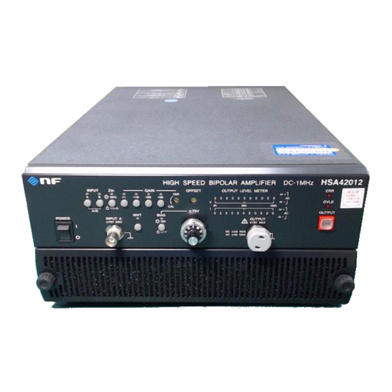
Figure 3-2. HSA42012 Front Panel
Figure 3-3. HSA42014 Front Panel
Rear Panel
Figure 3-4. HSA42011 Rear Panel
Figure 3-5. HSA42012 Rear Panel
Figure 3-6. HSA42014 Rear Panel
Indications at Power-On and Initialization
I/O Terminals
Input Connector: a (Front)/B (Rear)
Output Connector (Main Output)
Figure 3-7. How to Remove and Attach the BNC Cover
Monitor Output Connector
External Control I/O Connector
Table 3-1. List of External Control I/O Connector Pins
Figure 3-8. External Control I/O
Figure 3-9. Example for I/O Control by Using External Switch
I/O Connection
Signal Generator
Figure 3-10. Basic Connection Diagram
Signal Cords
Load
Examples of Basic Operations
Input Selection and Input Impedance Selection
Output Voltage Adjustment
Fine Output Offset Adjustment
Figure 3-11. CAL Position of Control for Fine Adjustment (VAR)
Figure 3-12. Center Position of Offset Fine Adjustment
DC Bias Addition
Output Polarity Switching
Output Voltage Monitoring
Output On/Off Control
Setting at Power-On
Table 3-2. List of DIP Switch Settings
Advanced Operations
Maximum Output Current and Operation Range
Figure 4-1. HSA42011 Operation Range
Figure 4-2. HSA42012 Operation Range
Figure 4-3. HSA42014 Operation Range
Figure 4-4. Current Waveform Asymmetric with Regard to Polarity
Increasing of Output Voltage by Balanced Output
Figure 4-5. Connection of Two Units
Troubleshooting
Error Messages
Errors at Power-On
Table 5-1. Diagnosis Performed at Power-On
Errors Related to the Protection Function
When Fault Symptoms Are Observed
Table 5-4. When Fault Symptoms Are Observed (1/2)
Table 5-5. When Fault Symptoms Are Observed (2/2)
Maintenance
Introduction
Daily Maintenance
Figure 6-1. Air Filter Cleaning Procedure
Storage, Repacking, and Transportation
Performance Testing
Measurement of Maximum Output Voltage (AC)
Figure 6-2. Measurement of Maximum Output Voltage (AC)
Measurement of Maximum Output Voltage (DC)
Figure 6-3. Measurement of Maximum Output Voltage (DC)
Measurement of Frequency Characteristics
Figure 6-4. Measurement of Frequency Characteristics
Measurement of Gain Accuracy
Measurement of Sine Wwave Distortion Ratio
Figure 6-5. Measurement of Sine Wave Distortion Ratio
Measurement of Bias-Added Voltage
Figure 6-6. Measurement of Bias-Added Voltage
Table 6-1. Judgment of HSA42011 / HSA42012 / HSA42014 Performance
Specifications
Input
Output
Monitor Output
Output LED Meter
Protection Function
External Control I/O
Output On/Off Control
Setting at Power-On
Power Input
Withstand Voltage, Insulation Resistance
Safety, EMC, and Rohs
Operating Environment
Figure 7-1. Ambient Temperature / Humidity Ranges
External Dimensions and Weight
Output Voltage / Current Range
Figure 7-2. HSA42011 Output Voltage / Current Range
Figure 7-3. HSA42012 Output Voltage / Current Range
Figure 7-4. HSA42014 Output Voltage / Current Range
External Dimensions
Figure 7-5. HSA42011 External Dimensions
Figure 7-6. HSA42012 External Dimensions
Figure 7-7. HSA42014 External Dimensions
Advertisement
Quick Links
Download this manual
HIGH SPEED BIPOLAR AMPLIFIER
HSA42011
HSA42012
HSA42014
INSTRUCTION MANUAL
NF Corporation
Table of
Contents
Previous
Page
Next
Page
1
2
3
4
5
Advertisement
Table of Contents
Need help?
Do you have a question about the HSA42012 and is the answer not in the manual?
Ask a question
Questions and answers
Related Manuals for NF HSA42012
Amplifier NF HSA42011 Instruction Manual
High speed bipolar amplifier (86 pages)
Amplifier NF HSA4051 Operation Manual
High speed bipolar (82 pages)
Amplifier NF HSA4014 Operation Manual
High speed bipolar (82 pages)
Amplifier NF HSA4012 Operation Manual
High speed bipolar (82 pages)
Amplifier NF HSA4052 Operation Manual
High speed bipolar (82 pages)
Amplifier NF HSA42014 Instruction Manual
High speed bipolar amplifier (112 pages)
Amplifier NF HSA42051 Instruction Manual
High speed bipolar amplifier (100 pages)
Amplifier NF HVA4321 Instruction Manual
(152 pages)
Amplifier NF BA4825 Instruction Manual
High speed bipolar amplifier (88 pages)
Amplifier NF CA5351 Instruction Manual
Programmable current amplifier (151 pages)
Amplifier NF SA-430F5 Instruction Manual
Low noise differential amplifier (46 pages)
Amplifier NF CA5350 Instruction Manual
Programmable current amplifier (110 pages)
Amplifier NF IV-202F4 Instruction Manual
Transimpedance amplifier (14 pages)
Amplifier NF SA-420F5 Instruction Manual
Low noise fet differential amplifier (46 pages)
Amplifier NF SA-240F5 Instruction Manual
Low noise fet amplifier (48 pages)
Amplifier NF SA-220F5 Instruction Manual
Low noise fet amplifier (44 pages)
This manual is also suitable for:
Hsa42011
Hsa42014
Table of Contents
Print
Rename the bookmark
Delete bookmark?
Delete from my manuals?
Login
Sign In
OR
Sign in with Facebook
Sign in with Google
Upload manual
Upload from disk
Upload from URL


Need help?
Do you have a question about the HSA42012 and is the answer not in the manual?
Questions and answers