Table of Contents
Advertisement
Quick Links
Advertisement
Table of Contents

Related Manuals for NF SA-430F5


Summary of Contents for NF SA-430F5
- Page 1 LOW NOISE DIFFERENTIAL AMPLIFIER SA-430F5 INSTRUCTION MANUAL NF Corporation...
- Page 3 DA00062391-001 LOW NOISE DIFFERENTIAL AMPLIFIER SA-430F5 INSTRUCTION MANUAL...
- Page 5 This chapter explains the basic operations of the panels. 4. Maintenance This chapter describes a method for simply inspecting operation. 5. Specifications This chapter gives specifications (functions and performance). 6. Reference Data This chapter shows the general electrical characteristics of a normal SA-430F5. SA-430F5...
- Page 6 ────Safety Information──── To ensure safe use, be sure to observe the following safety precautions. NF Corporation shall not be held liable for damages that arise from a failure to observe these safety precautions or warnings or cautions in the instruction manual.
- Page 7 42 Vpk or less for safety (this product is used grounded so the encl osure potential and ground potential are equal). Waste disposal For environmental protection, do not discard this product in domestic household waste. This product shall be disposed of through an appropriate industrial waste disposer. SA-430F5...
-
Page 8: Table Of Contents
External Dimensions of Bottom Plate ..............5-5 Reference Data ...................... 6-1 Reference Data ...................... 6-1 Equivalent Input Noise Voltage Density ............. 6-1 Noise Figure Frequency Characteristic (for 50 Ω system) ......... 6-2 Voltage Gain Frequency Characteristic ............... 6-2 Input VSWR Frequency Characteristic ............... 6-3 SA-430F5... - Page 9 Output VSWR Frequency Characteristic ............6-3 Reverse Transfer Gain Frequency Characteristic ..........6-4 CMRR Frequency Characteristic ................. 6-4 WARRANTY SA-430F5...
- Page 10 Figure 6-5 Output VSWR frequency characteristic from 100 kHz to 500 MHz ......6-3 Figure 6-6 Reverse transfer gain frequency characteristic from 1 kHz to 100 MHz ....6-4 Figure 6-7 CMRR frequency characteristic from 1 kHz to 100 MHz ........6-4 Table 2-1 List of contents ....................2-1 SA-430F5...
-
Page 11: Outline
1. Outline Overview ........................ 1-1 Features......................... 1-1 Operating Principle ....................1-2... -
Page 12: Overview
1.1 Overview Overview The SA-430F5 is an ultra-low-noise differential amplifier realizing both an equivalent input noise voltage density of 0.35 nV/ Hz and a noise figure of 1.1 dB at 50 Ω. Furthermore, it has 200 times gain and a wide bandwidth (400 Hz to 110 MHz) property for low impedance signal source of 50 Ω. -
Page 13: Operating Principle
The gain of A1 is 133 times and that of A2 is 3 times, so the total gain is 400 times (52 dB). The output impedance of this product is 50 Ω, so the gain of this product is 46 dB (200 times) for a 50 Ω load. Figure 1-1 Block diagram SA-430F5... -
Page 15: Preparation Before Use
2. Preparation before Use Check Appearance and Accessories..............2-1 Conditions for Installation Location ..............2-2 Power Supply ......................2-2 Connecting with Low Noise DC Power Supply LP Series ........2-3 Connecting to Power Supply other than LP Series ..........2-4... -
Page 16: Check Appearance And Accessories
When you take the contents out of the box, check them. If you find a deep scratch or dent on the product or an accessory is missing, report the problem to the NF Corporation or one of our representatives. -
Page 17: Conditions For Installation Location
・Stabilized DC power supply with ±15 V ±5 %, +15 V: +65 mA or higher, −15 V: −45 mA or higher (a switching power supply is not recommended). Attention This product will be damaged by reversely connecting the power supply. Supplying a voltage greater than ± 16.5 V will damage the internal circuits of this product. SA-430F5... -
Page 18: Connecting With Low Noise Dc Power Supply Lp Series
・Do not apply excessive force to the cable while the cable is connected to this product. The power supply pin of this product is easy to bend, and if strong force is applied, the pin may break (if it should be damaged, a repair fee will be charged) SA-430F5... -
Page 19: Connecting To Power Supply Other Than Lp Series
・Be sure to carefully reconfirm the polarity and voltage of the power supply. ・If the power supply is reversely connected or a voltage of higher than ± 16.5 V is applied, the internal circuits will be damaged. ・Use a DC power supply that restricts the current to 150 mA. SA-430F5... -
Page 21: Panel Features And Basic Operations
3. Panel Features and Basic Operations Panel Component Names and Functions ............3-1 Input Connection and Installation ..............3-3 Output Connection ....................3-4 Warm-up Time ...................... 3-4 Used for Single-Ended Input ................3-4... -
Page 22: Panel Component Names And Functions
Four plastic screws are attached to protect the case while the product is shipped from the factory. Remove them when attaching the bottom plate. The screw hole diameter for attaching the bottom plate is M3. Use metal screws (M3 pan head screw with a 4 mm length) when attaching it. SA-430F5... -
Page 23: Figure 3-1 Front And Rear Panel Views
3.1 Panel Component Names and Functions ④ ⑤ ⑥ ① ② ③ ⑦ Figure 3-1 Front and rear panel views SA-430F5... -
Page 24: Input Connection And Installation
Do not connect this product to an AC outlet because doing so is dangerous. The signal GND and case have the same electric potential. Caution is required when giving a potential to the case or signal GND because doing so may cause electric shock. SA-430F5... -
Page 25: Output Connection
When +INPUT is short-circuited, it will become an inverting amplifier, and when −INPUT is short-circuited, it will become a non-inverting amplifier. If you use a short plug other than supplied one, this product might affect the performance. SA-430F5... -
Page 27: Maintenance
4. Maintenance Before Maintenance ....................4-1 Consumption Current with No Signal ..............4-2 Non-Inverting Input Operation ................4-2 Inverting Input Operation ..................4-4... -
Page 28: Before Maintenance
This manual describes about operation check that can be easily performed to check if this product is normal. For advanced inspections, calibration, or maintenance, contact NF or our agent. For operation checks, items including the following measurement instruments and jigs are required. -
Page 29: Consumption Current With No Signal
10 kHz. If waveforms like those in Figure 4-2 are displayed on the oscilloscope, this is normal. Signal generator DC power supply ±15 V ± 100 mV at 10 kHz Sine wave 20dB attenuator50Ω) 50Ω power divider Short plug Oscilloscope Figure 4-1 Connection diagram for non-inverting input operation SA-430F5... -
Page 30: Figure 4-2 Non-Inverting Input Voltage Waveforms And Output Voltage Waveforms
4.3 Non-Inverting Input Operation Input 10 mV Upper waveform: 5 mV/DIV Lower waveform: 1 V/DIV Output −0.2 −0.1 [ms] Figure 4-2 Non-inverting input voltage waveforms and output voltage waveforms SA-430F5... -
Page 31: Inverting Input Operation
10 kHz. If waveforms like those in Figure 4-4 are displayed on the oscilloscope, this is normal. Signal generator DC power supply ±15 V ± 100 mV at 10 kHz Sine wave Short plug 20dB attenuator(50Ω) 50Ω power divider Oscilloscope Figure 4-3 Connection diagram for inverting input operation SA-430F5... -
Page 32: Figure 4-4 Inverting Input Voltage Waveforms And Output Voltage Waveforms
4.4 Inverting Input Operation Input 10 mV Upper waveform: 5 mV/DIV Lower waveform: 1 V/DIV Output −0.2 −0.1 [ms] Figure 4-4 Inverting input voltage waveforms and output voltage waveforms SA-430F5... -
Page 33: Specifications
5. Specifications Specifications ......................5-1 Non-destructive Maximum Ratings ..............5-1 Electrical Characteristics ..................5-1 5.2.1 Input ....................... 5-1 5.2.2 Output ......................5-2 5.2.3 Amplifier ......................5-2 5.2.4 Power Supply ....................5-3 General ........................5-3 External View......................5-4 External Dimensions of Bottom Plate ..............5-5... -
Page 34: Non-Destructive Maximum Ratings
0.35 nV/ Hz typical (10 kHz to 1 MHz) Noise figure (50 Ω systemes) (measured with HP 8970 B and HP 346 A) 1.25 dB or lower, 1.10 dB typical (at 10 MHz) 1.75 dB or lower, 1.40 dB typical (at 100 MHz) SA-430F5... -
Page 35: Output
±100 ppm/°C typical (at 20±10 °C) Reverse transfer gain −120 dB typical (at 10 MHz) −100 dB typical (at 100 MHz) 1 dB gain compression point +18 dBm typical (10 MHz to 100 MHz) Intercept point +28 dBm typical (at 68 MHz) SA-430F5... -
Page 36: Power Supply
68 (W) × 43 (D) × 28 (H) mm (without protrusions) Weight (net) Approx. 130 g Operating temperature and humidity ranges 0 to 40 °C, 10 to 90 %RH (non-condensation) Storage temperature and humidity ranges −10 to 50 °C, 10 to 80 %RH (non-condensation) SA-430F5... -
Page 37: External View
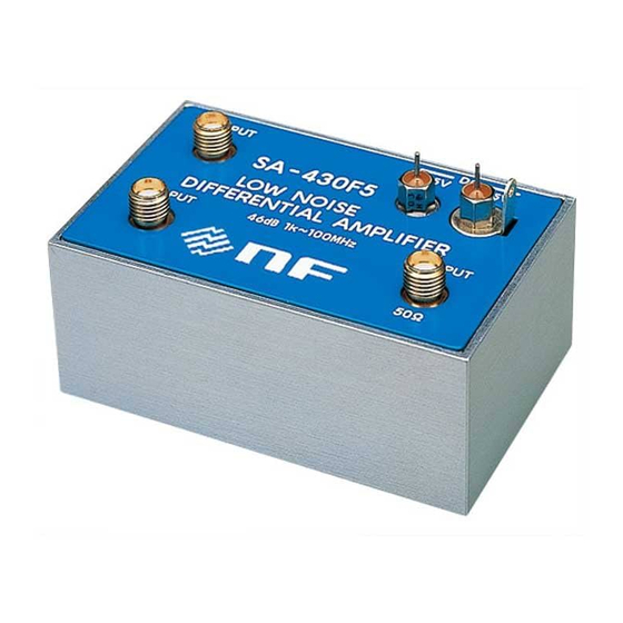
5.4 External View External View Figure 5-1 External view SA-430F5... -
Page 38: External Dimensions Of Bottom Plate
5.5 External Dimensions of Bottom Plate External Dimensions of Bottom Plate Figure 5-2 External dimensions of bottom plate SA-430F5... - Page 39 6. Reference Data Reference Data ...................... 6-1 Equivalent Input Noise Voltage Density ............. 6-1 Noise Figure Frequency Characteristic ............... 6-2 Voltage Gain Frequency Characteristic ............... 6-2 Output VSWR Frequency Characteristic ............6-3 Reverse Transfer Gain Frequency Characteristic ..........6-4...
-
Page 40: Reference Data
6.1 Reference Data Reference Data This chapter shows the general electrical characteristics of a normal SA-430F5. These data show the average values obtained by measuring the performance of individual products. The performance of this product may not achieve the level of these data, but all products have been strictly tested before shipment to check that they meet the specifications. -
Page 41: Noise Figure Frequency Characteristic (For 50 Ω System)
Noise Figure Frequency Characteristic (for 50 Ω system) 110M Frequency [Hz] Figure 6-2 Noise figure frequency characteristic from 10 MHz to 110 MHz Voltage Gain Frequency Characteristic Figure 6-3 Voltage gain frequency characteristic from 100 Hz to 200 MHz SA-430F5... -
Page 42: Input Vswr Frequency Characteristic
6.5 Input VSWR Frequency Characteristic Input VSWR Frequency Characteristic Figure 6-4 Input VSWR frequency characteristic from 100 kHz to 500 MHz Output VSWR Frequency Characteristic Figure 6-5 Output VSWR frequency characteristic from 100 kHz to 500 MHz SA-430F5... -
Page 43: Figure 6-6 Reverse Transfer Gain Frequency Characteristic From 1 Khz To 100 Mhz
6.7 Reverse Transfer Gain Frequency Characteristic Reverse Transfer Gain Frequency Characteristic Figure 6-6 Reverse transfer gain frequency characteristic from 1 kHz to 100 MHz CMRR Frequency Characteristic Figure 6-7 CMRR frequency characteristic from 1 kHz to 100 MHz SA-430F5... - Page 44 NF or an agent designated by NF. The purchaser shall prepay for all shipping charges, duties, and taxes for the product to either NF or an agent from another country, and the shipping charge for returning the product to the purchaser shall be paid by NF.
- Page 45 We assume no responsibility for influences resulting from the operations in this manual. Copyright 2017, NF Corporation SA-430F5 INSTRUCTION MANUAL NF Corporation 6-3-20, Tsunashima Higashi, Kohoku-ku, Yokohama...
- Page 46 NF Corporation 6-3-20, Tsunashima Higashi, Kohoku-ku, Yokohama 223-8508 JAPAN...
Need help?
Do you have a question about the SA-430F5 and is the answer not in the manual?
Questions and answers