Table of Contents
Advertisement
Quick Links
Advertisement
Table of Contents

Related Manuals for NF CA5350


Summary of Contents for NF CA5350
- Page 1 PROGRAMMABLE CURRENT AMPLIFIER CA5350 Instruction Manual NF Corporation...
- Page 3 DA00043807-003 PROGRAMMABLE CURRENT AMPLIFIER CA5350 Instruction Manual...
-
Page 5: Outline
This symbol contains information to avoid such risk. The scope of this Manual This manual describes the CA5350 that conform to requirements of CE Marking. Products without CE Marking affixed, may not meet derectives for CE Marking (EMC and others). - Page 6 ――― Safety Precautions ――― To ensure safe use, be sure to observe the following warnings and cautions. NF Corporation shall not be held liable for damages that arise from a failure to observe these warnings and cautions. This product is a Class I product (with protective conductor terminal) that conforms to the JIS and IEC insulation standards.
- Page 7 Using the product in wet condition may cause electric shock and fire. When water etc. get into the product, immediately pull out the power supply cord, and contact NF Corporation or one of our representatives from where you bought the product.
- Page 8 ──── Note on Waste Processing ──── To protect the environment, ensure that this device is disposed of by an appropriate industrial waste processor. This product does not use batteries or a backlight that contains mercury. CA5350...
-
Page 9: Table Of Contents
3.6.1 Basic Key Operations ................... 3-15 3.6.2 Simplified Operating Method When You Use Device for the First Time ..3-17 3.6.3 Initialization ....................3-18 3.6.4 Basic Settings ....................3-19 3.6.4.1 Input switching ..................3-19 3.6.4.2 Zero Check ....................3-19 CA5350... - Page 10 Remote Control Interface Selection ..............5-2 5.1.2 Outline of USB ....................5-3 5.1.2.1 Preparation of Controller ................5-3 5.1.2.2 Preparation of CA5350 ................5-3 5.1.2.3 USB Device Identification ................5-3 5.1.3 Outline of GPIB ....................5-4 5.1.3.1 Preparation of Controller ................5-4 5.1.3.2 Preparation of CA5350 ................
- Page 11 Specifications ......................8-2 8.1.1 Input section ....................8-2 8.1.2 Current suppression section ................8-3 8.1.3 Amplifier section ..................... 8-3 8.1.4 Output section ....................8-4 8.1.5 DC bias voltage output section ............... 8-4 8.1.6 General information ..................8-5 External Dimensions ....................8-7 CA5350...
- Page 12 Figure 3-11 When the signal source is grounded ............3-12 Figure 3-12 When the signal source cannot be grounded ..........3-12 Figure 3-13 CA5350 outline block diagram ..............3-20 Figure 3-14 Definition of the startup time ............... 3-22 Figure 4-1 Input circuit ..................... 4-2 Figure 4-2 Block diagram of current suppression .............
- Page 13 Table 6-2 List of error messages when operating the panel ..........6-3 Table 6-3 List of error messages during operation ............6-3 Table 6-4 List of error messages during remote control ........... 6-3 Table 6-5 When the device appears to be a problem ............6-4 CA5350...
- Page 14 1. OUTLINE Features ..............1-2 Applications ............1-2 List of Functions ............ 1-3 Principle of Operation ..........1-4 CA5350...
-
Page 15: Features
1.1 Features Features “CA5350 PROGRAMMABLE CURRENT AMPLIFIER” is the current input type preamplifier that converts the input current signal from photo multiplier or photo diode into voltage signal. It has both high gain and wide frequency band, and can be varied over a wide range from 10k (V/A) to 10G(V/A). -
Page 16: List Of Functions
1.3 List of Functions List of Functions The following shows the outline of functional tree of CA5350. Back light control Brightness adjustment Gain I/V gain Output amplifier gain Filter On, Off Rise time (manual, automatic) Current suppression On, Off, Auto... -
Page 17: Principle Of Operation
ZERO CHECK It disconnects the input connection and cut off the input current. It is used to check whether there is current output from the sensor, or output offset from CA5350 itself. CURRENT SUPPRESSION It is equipped with CURERNT SUPPRESSION for canceling the offset current of the sensor. - Page 18 DC voltage in the range of -8V to +8V (resolution 0.001V) will be useful. SYSTEM CONTROLLER System controller sets and controls the analog parts according to user operations, and it displays various information on the front panel LCD. Besides, it can also communicate (remote I/F control) with the host controller. CA5350...
-
Page 19: Preparations Before Use
2.2.2 Installation Conditions ............. 2-3 2.2.3 Rack Mounting ................ 2-4 Grounding and Power Supply Connection ........2-13 Simplified Operation Check ............2-15 2.4.1 Checking operation and display at power on ......2-15 2.4.2 Checking key operation and response ........2-15 Calibration .................. 2-16 CA5350... -
Page 20: Checking Before Use
Checking Before Use Safety check Before using CA5350, make sure you have read “Safety Precautions”, Located at the beginning of this instruction manual and observe the required cautions. Before turning the power on, read “2.3 Grounding and Power Supply Connection” and observe the necessary cautions. -
Page 21: Installation
CAUTION Take the following precautions to prevent damage to CA5350. CA5350 is cooled by forced air-cooling. When you find that the fan has stopped, turn off the power switch immediately and please contact NF Corporation or one of our representatives. Using the product with the fan stopped may increase the damage, thus makes the repair impossible. -
Page 22: Rack Mounting
2.2 Installation 2.2.3 Rack Mounting CA5350 can be mounted on a 19-inch IEC rack, an EIA specification rack or a JIS standard rack by the use of a rack-mount kit (optional). The rack-mount kit is available with metric (JIS) type and inch (EIA) type. -
Page 23: Figure 2-1 Dimensional Drawing Of Rack-Mount (Eia, For 1 Unit)
2.2 Installation Figure 2-1 Dimensional drawing of rack- mount (EIA, for 1 unit) CA5350... -
Page 24: Figure 2-2 Dimensional Drawing Of Rack-Mount (Eia, For 2 Units)
2.2 Installation Figure 2-2 Dimensional drawing of rack- mount (EIA, for 2 units) CA5350... -
Page 25: Figure 2-3 Dimensional Drawing Of Rack-Mount (Jis, For 1 Unit)
2.2 Installation Figure 2-3 Dimensional drawing of rack- mount (JIS, for 1 unit) CA5350... -
Page 26: Figure 2-4 Dimensional Drawing Of Rack-Mount (Jis, For 2 Units)
2.2 Installation Figure 2-4 Dimensional drawing of rack- mount (JIS, for 2 units) CA5350... -
Page 27: Figure 2-5 Assembly Drawing Of Rack-Mount Kit (Eia, For 1 Unit)
2.2 Installation Figure 2-5 Assembly drawing of rack-mount kit (EIA, for 1 unit) CA5350... -
Page 28: Figure 2-6 Assembly Drawing Of Rack-Mount Kit (Eia, For 2 Units)
2.2 Installation Figure 2-6 Assembly drawing of rack- mount kit (EIA, for 2 units) 2-10 CA5350... -
Page 29: Figure 2-7 Assembly Drawing Of Rack-Mount Kit (Jis, For 1 Unit)
2.2 Installation Figure 2-7 Assembly drawing of rack- mount kit (JIS, for 1 unit) 2-11 CA5350... -
Page 30: Figure 2-8 Assembly Drawing Of Rack-Mount Kit (Jis, For 2 Units)
2.2 Installation Figure 2-8 Assembly drawing of rack-mount kit (JIS, for 2 units) 2-12 CA5350... -
Page 31: Grounding And Power Supply Connection
Before connecting the device to the power supply, make sure the protective grounding terminal is grounded. The protective grounding terminal for CA5350 is the grounding pin of the three-pole power cord. Make sure you insert the power cord’s plug into a three-pole power outlet with a protective grounding contact. - Page 32 Connect the power after checking that voltage of power socket is within the range of specified volage. Otherwise, it may damage CA5350. The power cord supplied with this equipment is designed to be used for this equipment only. Do not use this power cord for other equipment or purposes.
-
Page 33: Simplified Operation Check
For more detailed checking methods → Refer to “7. MAINTENANCE”. 2.4.1 Checking operation and display at power on When power supply of CA5350 is turned on, LCD will be initialized, startup screen will appear, and equipment will become operational. For the display when power is turned. -
Page 34: Calibration
2.5 Calibration Calibration Recommend that perform the Calibration for CA5350 at least once a year, regardless of the use environment and use frequency. When calibration is necessary, please contact NF Corporation or one of our representatives. You will be liable for the costs of calibration or adjustment. -
Page 35: Panel Features And Basic Operations
3.5 Operation Tree ....................3-13 3.6 Basic Operation Examples ................3-15 3.6.1 Basic Key Operations ................. 3-15 3.6.2 Simplified Operating Method When You Use Device for the First Time ..3-17 3.6.3 Initialization ....................3-18 3.6.4 Basic Settings .................... 3-19 CA5350... -
Page 36: Panel Component Names And Functions
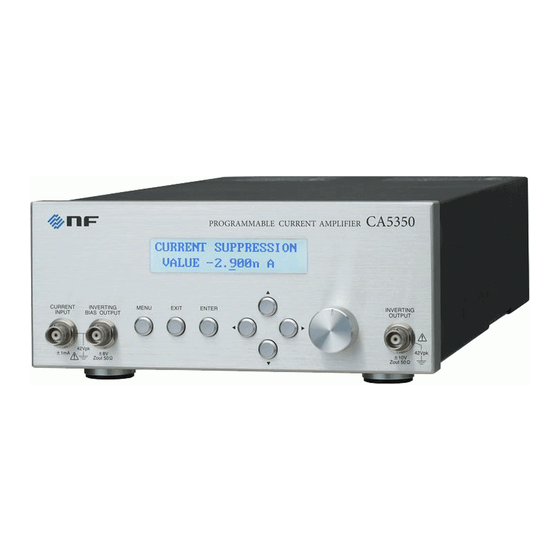
3.1 Panel Component Names and Functions Panel Component Names and Functions This section describes the names and functions of the components on the front and rear panel of CA5350. 3.1.1 Front panel Display Knob Display the setting and various information. -
Page 37: Rear Panel
Power input GPIB connector USB connector Power supply On/Off switch Pushing I side turns the power on, pushing O side turns it off. Fuse holder Spare fuse is also stored in it. Figure 3-2 Rear panel CA5350... -
Page 38: Display At Power "On" And Initial Setting
First, Take necessary preparation before usage/operation according to “2. PREPARATIONS BEFORE USE”. When the power switch is turned on, a test pattern is displayed, and then a startup message including the model name “CA5350” and firmware version is displayed (see below). Example: C A 5 3 5 0 V e r 1 . -
Page 39: Table 3-1 Setting Items And Initial Values List
3.2 Display at Power “ON” and Initial Setting 3.2.2 Initialization CA5350 is reset to the factory default settings in the following cases: At the time of shipment from factory All settings are initial values. When setting in memory number 0 is recalled In setting memory No. -
Page 40: I/O Terminals
INVERTING BIAS OUTPUT Enclosure 筐体 Figure 3-3 I/O Terminals CURRENT INPUT, INVERTING OUTPUT, and INVERTING BIAS OUTPUT of CA5350 are electrically insulated from the enclosure. Withstanding voltage is 42Vpk (DC + ACpeak). WARNING For avoiding electric shocks, ensure that voltage exceeding 42Vpk (DC+AC peak) should not be applied between the grouding of BNC connecters and enclosure. -
Page 41: Figure 3-4 Input Terminal
3.3 I/O Terminals Input terminal (CURRENT INPUT) Input terminal of CA5350 is located at two places, the front panel and the rear panel. Select and use either of them. You cannot use both input terminals simultaneously. Turning on ZERO CHECK will disconnect the input connector (the selected one from front and rear) from the internal amplifier. -
Page 42: Figure 3-7 Dc Bias Voltage Output Terminal
INVERTING BIAS OUTPUT Figure 3-7 DC bias voltage output terminal Voltage with the opposite polarity of DC bias voltage value set in CA5350 will be output from INVERTING BIAS OUTPUT connector. For a typical connection with the sensor is made, the center pin of input connector (CURRENT INPUT) is considered as plus polarity, while the center pin of DC bias voltage output connector (INVERTING BIAS OUTPUT) applies minus bias voltage to the sensor. -
Page 43: I/O Connection
Please do it as the following method. Install CA5350 as close as possible to sensor or the source of signal, and keep the connection cable of CURRENT INPUT and INVERTING BIAS OUTPUT as short as possible. -
Page 44: Connection Of Optical Sensor (Photodiode)
Figure 3-9 Connection of reverse bias type sensor Keeping the DC bias voltage setting in CA5350 is minus (0V or less) will apply reverse bias (plus to cathode, minus to anode) to the sensor shown in “Figure 3-9 Connection of reverse bias type sensor”. - Page 45 3.4 I/O Connection (3) Example of connection with photomultiplier (PMT) Because large bias voltage (hundreds of Volts) is required, dedicated power supply for bias voltage will be necessary. CA5350 INVERTING BIAS CURRENT OUTPUT INPUT Coaxial cable 同軸ケーブル Figure 3-10 Example of connection with a photomultiplier For either of connections, to get the best noise performance, it is important to make the input cable as short as possible.
-
Page 46: Connection With Lock-In Amplifier, Etc
Because I/O of CA5350 is insulated from the enclosure, it is difficult to be affected by ground loop. However, it is necessary to pay careful attention to the grounding of equipments connected to the output of sensor or CA5350. -
Page 47: Operation Tree
3.5 Operation Tree Operation Tree The operation tree when CA5350 is operated from the panel is shown below. BACKLIGHT : {LCD Backlight brightness setting menu} INPUT : {Input select menu FRONT/REAR} GAIN : {Gain setting menu} : {I/V gain} I/V GAIN : {Output amplifier gain} ×10 GAIN... - Page 48 REMOTE CONTROL : {Remote interface setting menu} :{GPIB address setting} ADDRESS RETURN TO LOCAL : {Return to local state from remote state} UTILITIES : {System information display} {Firmware Version display} {Device name display} {USB ID display} Self diagnosis 3-14 CA5350...
-
Page 49: Basic Operation Examples
I / V G A I N X 1 0 G A I N Pressing the EXIT key will return to the one higher hierarchy menu. Repetitively pressing the EXIT key will return the display to the top level menu. 3-15 CA5350... - Page 50 +20.34µA, and operating the key or rotating the knob in ▾ counterclockwise direction will decrease the current value to +18.34µA. In the case of numerical value, the change will be applied even if the ENTER key is not pressed. 3-16 CA5350...
-
Page 51: Simplified Operating Method When You Use Device For The First Time
Either front or rear output connector can be used. Because ZERO CHECK of CA5350 is still ON, signal from sensor has not been input to CA5350. Therefore, output voltage is almost 0V regardless of the sensor current. -
Page 52: Initialization
ENTER key for reset to the settings at Power ON. For CA5350, all settings will be reset as saved in memory No.1. CA5350 will be automatically reset to the settings you saved to memory NO.1 last time after turning the power on. -
Page 53: Basic Settings
Turn ZERO CHECK OFF, when amplifying signal from the sensor. Note that it will not be amplified if the ZERO CHECK is ON. 3.6.4.3 Gain Setting There are two types gain available in CA5350, namely I/V GAIN and ×10 GAIN (the gain of output amplifier). I/V GAIN Setting This is the gain of current-to-voltage conversion. -
Page 54: Figure 3-13 Ca5350 Outline Block Diagram
INVERTING OUTPUT ×10 Figure 3-13 CA5350 outline block diagram When SNR is very important for you, setting I/V GAIN as large as possible, and ×10 GAIN (output amplifier gain) to ×1 would help. When high speed response is needed, you can set output amplifier gain to ×10, and set I/V GAIN to a low value. -
Page 55: Table 3-2 I/V Gain Settings And Auto-Filter Settings
Any random filter setting can be made irrespective of I/V GAIN settings. However, overall response time of CA5350 is the combination of the response of I/V GAIN and the response time fo filter. Generally, it will be decided by the one with longer response time. - Page 56 3.6 Basic Operation Examples (Reference material) About rise time Rise time is defined as the time taken by output signal of CA5350 to change from 10% to 90% of the amplitude of an ideal square-wave (rise time=0s) input signal. Rise time 立上時間...
-
Page 57: Filter Setting
Relation between the filter rise time and -3dB cutoff frequency is shown below (theoretical values). Table 3-4 Filters’ rise time and bandwidth Filter setting -3dB cutoff frequency 1µs 340kHz 3µs 114kHz 10µs 34kHz 30µs 11.4kHz 100µs 3.4kHz 300µs 1.14kHz 340Hz 114Hz 10ms 34Hz 30ms 11.4Hz 100ms 3.4Hz 300ms 1.14Hz 3-23 CA5350... -
Page 58: Advanced Operations
Saving/Recalling the Settings ..........4-7 Self-diagnosis ................4-8 Adjusting the LCD Backlight Brightness ........4-9 Checking Various Information ..........4-10 4.7.1 Checking the Version ............4-10 4.7.2 Checking the Production Number ........4-10 4.7.3 Checking USB related ID ..........4-10 CA5350... -
Page 59: Zero Check
Shown as Figure4-1, the load of sensor is kept as low impedance, and input of CA5350 is turned off. By adjusting CURRENT SUPRESSION (manual only) and turning the output voltage of CA5350 to 0V, if ZERO CHECK is turned OFF, it will be possible to cancel the offset occurring in CA5350. -
Page 60: Cancelling The Dark Current Of Sensor
It is equipped with current source for cancelling the dark current of sensor and for removing the offset component of CA5350 itself. If the dark current of sensor is cancelled, gain of CA5350 can be set to even larger value, and measurement sensitivity can be improved. -
Page 61: Manually Setting The Current Value To Be Cancelled
S U P P R E S S I O N A U T O S R C H During auto current suppression, an irregular voltage with the value in range of -15 to 15V will be output to the output terminal of CA5350. CA5350... - Page 62 When over input is detected, auto current suppression will not run. If over input is detected in CA5350 because of large I/V gain and large dark current of sensor, the following message will appear and auto current suppression will not run.
-
Page 63: Setting Dc Bias Voltage
DC bias voltage is set to +1.2V. Current suppression, input 電流サプレッション, select, etc. are omitted. 入力切替などは省略 I/V GAIN CURRENT INPUT センサ Sensor (0V) To Filter フィルタ部へ INVERTING +1.2V BIAS OUTPUT DC bias voltage DCバイアス電圧 (-1.2V) setting: +1.2V 設定:+1.2V Figure 4-3 Connecting to DC bias voltage CA5350... -
Page 64: Saving/Recalling The Settings
4.4 Saving/Recalling the Settings Saving/Recalling the Settings CA5350 can save and recall up to 10 sets of settings. In these 10 sets, one set is factory default settings and it cannot be changed. Saving the setting in memory Select the Menu CONFIGURATION–SAVE, and set the memory number to be saved. -
Page 65: Self-Diagnosis
If error occurs again even after restarting the power supply, there is a possibility of malfunction of CA5350. Turn off the power switch, remove the power supply cord from the body, and contact NF Corporation or one of our representatives. -
Page 66: Adjusting The Lcd Backlight Brightness
4.6 Adjusting the LCD Backlight Brightness Adjusting the LCD backlight Brightness LCD backlight brightness of CA5350 can be adjusted in 3 stages including off. Turn it off when light disturb the measurement, such as using in a dark room. Even it is turned off, if the surrounding area is somewhat bright, you can see the display of LCD. -
Page 67: Checking Various Information
4.7 Checking Various Information Checking Various Information 4.7.1 Checking the Version Version of CA5350 is displayed when turning on the power supply. Besides, it can also be checked from Menu UTILITIES–VERSION. U T I L I T I E S V E R S I O N 1 . -
Page 68: Remote Control
Switching between Remote State and Local State ... 5-6 Response to Interface Message ......5-7 Service Request and Status Byte ......5-8 5.4.1 Service Request ..........5-8 5.4.2 Status Byte ............5-8 Commands Explanation .......... 5-9 Description of Individual Command ....... 5-11 Multiline Interface Messages ......... 5-22 CA5350... -
Page 69: Preparations Before Use
The connectors of respective interface are located on the rear panel of the CA5350. 5.1.1 Remote Control Interface Selection Either USB or GPIB can be used as an interface for remote control of CA5350. You cannot use both interfaces simultaneously. Accessing CA5350 simultaneously from both interfaces will cause CA5350 and host computer crashed, and you will have to reboot (turning on the power supply once again) them. -
Page 70: Outline Of Usb
Install the USB CDC driver in the computer that is used to control the product. USB CDC: Universal Serial Bus Communication Device Class It is possible to download the CA5350 USB CDC driver install file from NF corporation web site. -
Page 71: Outline Of Gpib
5.1.3.2 Preparation of CA5350 For the GPIB, the device in the system is identified by the unique address. Set unique GPIB address for each equipment. The GPIB address of the CA5350 is set through the procedure given below. GPIB address setting Select ADDRESS with the REMOTE menu, and the GPIB address setting menu as shown below is displayed. -
Page 72: Basic Specifications Of Gpib
Input buffer size is 128 bytes. Ensure that do not send program message exceeding this size in one time. When an inappropriate command is received, it will result in error and program messages will be stopped executing before receiving X Command. CA5350... -
Page 73: Switching Between Remote State And Local State
For GPIB interface, sending the GTL command from the controller or making REN line to a logical false, CA5350 will be back to local. If the GPIB cable is disconnected, the REN line becomes false and CA5350 will be back to local. Similarly, disconnecting the USB cable causes the product to be returned to the local state. -
Page 74: Response To Interface Message
[LOCAL] operation on the panel. (only GPIB) < Go To Local > Selects the local state (only GPIB) As for how to send an interface message from the controller, it differs depending on the device driver. For details, refer to instruction manual of each driver. CA5350... -
Page 75: Service Request And Status Byte
5.4.1 Service Request Service Request (SRQ) is the function for setting the signal wire of SRQ of bus line to Low (=True) and allocating it to controller when issue of SRQ is permitted and CA5350 is in the following states. -
Page 76: Commands Explanation
5.5 Command Explanation 5.5 Commands Explanation Commands of CA5350 are composed of one alphabet header and 0 ~ 2 parameters. When there is no parameter after the command, it will be interpreted as default parameters defined for that command. Priority of command execution Commands are stored in buffer in the sequence they are received. - Page 77 ◎ At the time of input, reading zero or space is ignored. When number before the decimal point is omitted, numerical value of the integer part is interpreted as 0. ◎ At the time of output, reading zero is space. ◎ Same as NR2 format. Example: +0.1234E+03 -50.0E-6 1.8E-9 5-10 CA5350...
-
Page 78: Description Of Individual Command
5.6 Description of Individual Commands 5.6 Description of Individual Command “Table 5-2 Header List” shows the list of headers for the commands of CA5350. Table 5-4 Header List Functions Header Description page LCD Backlight Brightness Adjustment 5-12 Voltage Bias ON/OFF... - Page 79 When the character string is less than 20 characters long, the remaining spaces will be filled with blank. When the string exceeds 20 characters, only first 20 characters will be displayed. Following display is possible characters. !"#$%&'()*+,-./ 0123456789:;<=>? @ABCDEFGHIJKLMNOPQRSTUVWYZ[\]^_ `abcdefghijklmnopqrstuvwyz{|}~ (blank) 5-12 CA5350...
- Page 80 H20 EXIT H21 ENTER H22 MENU Remarks: This will perform the same processes as pressing the front panel keys of CA5350. For parameters other than above, it will result in error. I – Input select Description: Input connector select Setting:...
- Page 81 Not used bit6 Not used bit7 Remarks: When more than one reason occurred causing mask bit be 1, CA5350 will send SRQ to controller. This function is only for GPIB, and it cannot be used with USB. 5-14 CA5350...
- Page 82 Gains can be set as above only when the output amplifier gain is ×1. When output amplifier gain is set to ×10, total gain will be 10 times of the value set by this command. Settings except the above will cause error. 5-15 CA5350...
- Page 83 Current Suppression was aborted. T – Filter Rise Time Setting Description: Filter rise time setting Setting: 1µs 3µs 10µs (factory default setting) 30µs 100µs 300µs 10ms 30ms 100ms 300ms Remarks: Filter is set to ON/OFF with P Command. 5-16 CA5350...
- Page 84 ±8nA range 0.000 E-09 ±80nA range 00.00 E-09 ±800nA range 000.0 E-09 ±8µA range 0.000 E-06 ±80µA range 00.00 E-06 ±800µA range 000.0 E-06 Remarks: For message terminator refer to Y command, and for EOI refer to K command. 5-17 CA5350...
- Page 85 5.6 Description of Individual Commands U0 – Queries of CA5350 Setting Description: Output for the CA5350 setting. Response message: C A 5 3 5 0 A 0 B 0 C 0 H 2 1 I0 J 0 K 0 M 0 0 1 N 2 P 1 R 0 9 S 0 5 T . W 0 Y 3 Z 0 < t e r m >...
- Page 86 Voltage bias value 4 digits after the decimal point Polarity '+' or '-' Header indicating voltage bias 'V' fixed Remarks: Voltage value read is the value set using V command or on the panel irrespective of whether bias is ON/OFF. 5-19 CA5350...
- Page 87 5.6 Description of Individual Commands U3 – Queries of Total Gain Description: Output the CA5350 total Gain Response message: 1 E 0 9 V/A < t e r m > Message terminator, EOI Unit of gain Fixed at "V/A"...
- Page 88 Auto Filter OFF (factory default setting) Remarks: Turning ON the auto filter will automatically set the filter according to I/V gain settings irrespective of the filter settings made with T command. For details, refer to ”3.6.4.3 Filter Setting”. 5-21 CA5350...
-
Page 89: Multiline Interface Messages
PPU : Parallel Poll Unconfigure GTL : Go To Local SPE : Serial Poll Enable SDC : Selected Device Clear SPD : Serial Poll Disable PPC : Parallel Poll Configure UNL : Unlisten GET : Group Execute Trigger UNT : Untalk 5-22 CA5350... -
Page 90: Troubleshooting
Error Messages ............. 6-2 6.1.1 Errors at Power ON .......... 6-2 6.1.2 Errors at Panel Operation ......... 6-3 6.1.3 Error during Operation ........6-3 6.1.4 Errors in Remote Control ........6-3 When the Device Appears to be a Problem ... 6-4 CA5350... -
Page 91: Error Messages
When the repair is required, please contact NF Corporation or one of our representatives. When you request the repair of CA5350, please let us know the content of an error message if it is displayed. An error message not listed in this instruction manual may be displayed due to a malfunction caused by strong external noise. -
Page 92: Errors At Panel Operation
The following error messages may appear during remote control. Table 6-4 List of error messages during remote control Error message Content and Cause Content and Cause Incorrect syntax in the Send the correct program REMOTE ERROR program code or parameter out code. of range error detected. CA5350... -
Page 93: When The Device Appears To Be A Problem
When the device appears to be a problem, check the following table to see if a solution is given. When the problem is not solved or the device cannot be recovered after the corrective action was taken, please contact NF Corporation or one of our representatives. -
Page 94: Maintenance
7.3 Storage, Repackaging, and Transport ........7-3 7.4 Checking the Version Number ..........7-3 7.5 Performance Testing ............. 7-4 7.5.1 Current suppression setting accuracy, gain accuracy ..7-5 7.5.2 Output offset voltage ............7-6 7.5.3 DC bias voltage setting accuracy ........7-6 Calibration ................7-7 CA5350... -
Page 95: Introduction
Check if the device operates properly. Performance testing: Check if the device respects the rated values. Adjustment, calibration: If the rated values are not satisfying, NF Corporation will make the necessary adjustment or calibration to restore performance. Damage repairs:... -
Page 96: Storage, Repackaging, And Transport
When using a transportation vendor, instruct the vendor that this product is a precision device. Checking the Version Number The version number of CA5350 firmware is displayed after power-on. → Refer to “3.2.1 Display at power ON”. Version display It is also display the version number on LCD by operating the keys located on the front panel. -
Page 97: Performance Testing
Performance Testing Performance testing is conducted as part of preventive maintenance to prevent performance degradation of the CA5350. Besides, conduct it if needed after acceptance inspection, periodic inspection or repair. If the result of a performance testing does not meet the specifications, calibration or repair is required. -
Page 98: Current Suppression Setting Accuracy, Gain Accuracy
In this section, easy to measures the total accuracy of the setting accuracy of current suppression and gain accuracy of amplifier. For the exact test, please ask a test to the NF Corporation. Connection: Connect INVERTING OUTPUT (Front) to DC voltmeter to BNC cable... -
Page 99: Output Offset Voltage
Values indicated on DC bias voltage setting Specification DC voltmeter -8.000V +7.900V ~ +8.100V ±(1%+20mV) 0.000V -20mV ~ +20mV ±20mV +8.000V -8.100V ~ -7.900V ±(1%+20mV) Note: Voltage of reverse polarity of the setting will appear. CA5350... -
Page 100: Calibration
7.6 Calibration Calibration If the performance test does not satisfy the specification, NF Corporation will make the necessary adjustment or calibration to recover the performance. If calibration is necessary, contact NF Corporation or one of our representatives. You will be liable for the costs of adjustment and calibration outside the warranty period. - Page 101 Output section ..........8-4 8.1.5 DC bias voltage output section ......8-4 8.1.6 General information .......... 8-5 External Dimensions ..........8-7 Supplementary value: This value implies supplementary data of the product and it does not guarantee the product performance. CA5350...
-
Page 102: Specifications
Gain setting (V/A) Remarks current noise density 2.5fA/√Hz at 55Hz 6fA/√Hz at 200Hz 100M 15fA/√Hz 45fA/√Hz at 1kHz 150fA/√Hz 100k 750fA/√Hz 6pA/√Hz Conditions: Input open, Front input, Filter 300µs (10G V/A) or 30µs (1G V/A ~ 10k V/A), no source capacitance CA5350... -
Page 103: Current Suppression Section
DC ~ 14kHz 25µs Reference frequency: 1Hz DC ~ 70kHz 5µs Reference frequency: 10Hz 100M DC ~ 175kHz 2µs DC ~ 350kHz 1µs DC ~ 500kHz 0.7µs 100k Response speed is the rise time (10%–90%) of square output response waveform. CA5350... -
Page 104: Output Section
±2mA Total current of front and rear connectors Output impedance 50Ω (supplementary value) DC bias will output voltage with inverted polarity. Example: When +1.000V is set, -1.000V will be output in the DC bias voltage output BNC connector. CA5350... -
Page 105: General Information
AC100V / 120V / 220V / 240V ±10% However, 250V or less Frequency 50Hz/60Hz ±2Hz Power consumption 40VA or less Overvoltage category Cooling of device Forced cooling, rear panel discharge type Setting posture Horizontal (10° or less) CA5350... - Page 106 EN61010-1 EN61010-2-030 EMC EN61326-1 (Group 1, Class A) EN61326-2-1 EN61000-3-2 EN61000-3-3 RoHS directive Directive 2011/65/EU External dimensions Approx. 216 (W) × 88 (H) × 400 (D) mm, not including protuberances Weight Approx.5.0kg (not including accessories) CA5350...
-
Page 107: External Dimensions
8.2 External Dimensions External Dimensions Figure 8-1 CA5350 External Dimensions CA5350... - Page 108 NF Corporation will repair such defective product free of charge, if the purchaser contact s NF Corporation or one of our representatives within the warranty period.
- Page 109 However, we assume no responsibility for any damage regarding the contents of the instruction manual. If you have any uncertainty or you found an error or omission, please contact NF Corporation or one of our representatives from which you purchased the product. CA5350 Instruction Manual...
- Page 110 NF Corporation 6-3-20 Tsunashima Higashi, Kohoku-ku, Yokohama 223-8508, JAPAN Phone: +81-45-545-8128...
Need help?
Do you have a question about the CA5350 and is the answer not in the manual?
Questions and answers