GW Instek SPS-1230 User Manual
Dc power supply
Hide thumbs
Also See for SPS-1230:
- User manual (28 pages) ,
- Instruction manual (3 pages) ,
- Manual (31 pages)

Subscribe to Our Youtube Channel
Related Manuals for GW Instek SPS-1230


Summary of Contents for GW Instek SPS-1230
- Page 1 DC Power Supply SPS-1230/1820/3610/2415/606 USER MANUAL GW INSTEK PART NO. 82PS-36100MJ1 ISO-9001 CERTIFIED MANUFACTURER...
- Page 2 This manual contains proprietary information, which is protected by copyrights. All rights are reserved. No part of this manual may be photocopied, reproduced or translated to another language without prior written consent of Good Will company. The information in this manual was correct at the time of printing. However, Good Will continues to improve products and reserves the rights to change specification, equipment, and maintenance procedures at any time without notice.
-
Page 3: Table Of Contents
TABLE OF CONTENTS Table of Contents SAFETY INSTRUCTION ............. 4 OVERVIEW ................ 9 Main Features ........10 Model Differences ....... 10 Front Panel Overview ......11 Rear Panel Overview ......13 CV/CC Crossover Characteristics ..15 Output Current/Temperature Characteristics ........16 SETUP ................ -
Page 4: Safety Instruction
SPS Power Supply User Manual AFETY INSTRUCTION This chapter contains important safety instructions that you must follow when operating the SPS power supply and when keeping it in storage. Read the following before any operation to insure your safety and to keep the power supply in the best possible condition. - Page 5 SAFETY INSTRUCTION Do not dispose electronic equipment as unsorted municipal waste. Please use a separate collection facility or contact the supplier from which this instrument was purchased. Safety Guidelines Do not place heavy objects on the power supply. General Guideline Avoid severe impact or rough handling that CAUTION may damage the power supply.
- Page 6 SPS Power Supply User Manual Fuse type: 115V input: T 10A 250V; 230V input: Fuse T 6.3A 250V WARNING To ensure fire protection, replace the fuse only with the specified type and rating. Disconnect the power cord before replacing the fuse.
- Page 7 SAFETY INSTRUCTION Location: Indoor Storage environment Relative Humidity: < 70% Temperature: -10°C to 70°C Do not dispose this instrument as unsorted Disposal municipal waste. Please use a separate collection facility or contact the supplier from which this instrument was purchased. Please make sure discarded electrical waste is properly recycled to reduce environmental impact.
- Page 8 SPS Power Supply User Manual Power cord for the United Kingdom When using the SPS in the United Kingdom, make sure the power cord meets the following safety instructions. NOTE: This lead/appliance must only be wired by competent persons WARNING: THIS APPLIANCE MUST BE EARTHED IMPORTANT: The wires in this lead are coloured in accordance with the following code: Green/ Yellow:...
-
Page 9: Overview
OVERVIEW VERVIEW This chapter describes the SPS series of power supplies, including their main features and front / rear panel introduction. After going through the overview, follow the Setup chapter (page 17) to properly power up and set operation environment. For initial inspection, refer to the Performance adjustment chapter (page27). -
Page 10: Main Features
230V (195V~265V) High frequency switching power High power Density High efficiency (70%) Constant voltage and constant current operation Remote output control (on/off) Model Differences Input Ratting Input Ratting Model name Voltage Current Watts Watts SPS-1230 SPS-1820 SPS-2415 SPS-3610 SPS-606... -
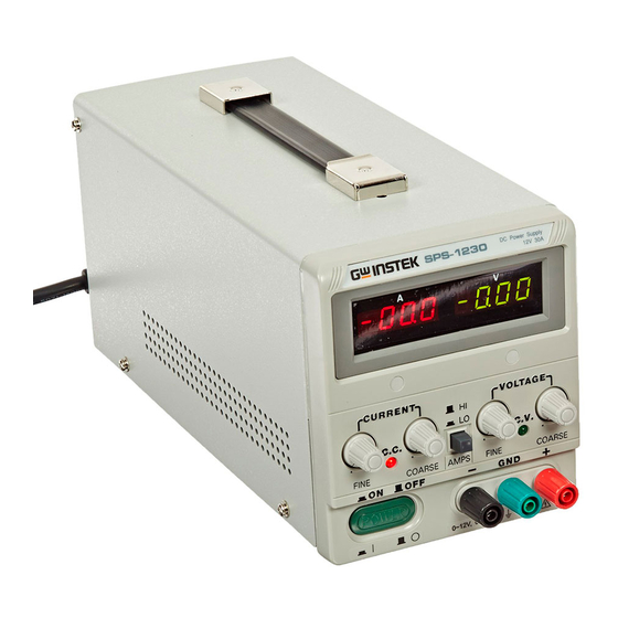
Page 11: Front Panel Overview
OVERVIEW Front Panel Overview The constant voltage indicator Constant voltage indicator lights up when the power supply is in constant voltage mode. Constant current The constant current indicator indicator lights up when the power supply is in constant current mode. Fine current knob Used for fine adjustment of the current output. - Page 12 SPS Power Supply User Manual Course voltage Used for coarse adjustment of the knob voltage output. Positive output Positive polarity terminal terminal Negative output Negative polarity terminal terminal Ground terminal Ground terminal Current Display Displays the current output Voltage display Displays the voltage output Power switch Range selector...
-
Page 13: Rear Panel Overview
OVERVIEW Rear Panel Overview Overvoltage adjustment Sense Terminal Remote control Positive output AC line selector Ground Negative output Power socket and fuse Fuse holder 115V input: T 10A 250V; 230V Power Socket input: T 6.3A 250V AC line select 115V / 230V AC line select Voltage –sense Sense S+, S- terminal... - Page 14 SPS Power Supply User Manual Ground Positive output terminal Negative output terminal OVP adjuster Overvoltage protection adjustment Remote control Remote control jumper. terminal Open = Remote output off Short = remote output on...
-
Page 15: Cv/Cc Crossover Characteristics
OVERVIEW CV/CC Crossover Characteristics SPS power supplies automatically switch between Background constant voltage mode (CV) and constant current mode (CC), according to the load conditions. When the current level is smaller than the output setting, SPS operates in Constant Voltage mode. The C.V. indicator on the front panel turns green. -
Page 16: Output Current/Temperature Characteristics
SPS Power Supply User Manual Output Current/Temperature Characteristics The chart below shows the current output Background characteristics versus temperature. Diagram... -
Page 17: Setup
SETUP ETUP This chapter describes how to properly power up and configure SPS before operation. For checking the functionality, refer to the Performance verification chapter, page27. Installation Installation Location ........18 Power Power Up ............18 Over Voltage Protection Set Up ....... 19 Load Wire Load Cable Connection ........ -
Page 18: Installation Location
SPS Power Supply User Manual Installation Location Please ensure there is adequate ventilation and Ventilation and cooling fan that the cooling fan has enough clearance to allow clearance adequate airflow. Power Up Press the Power switch to Power On turn on the power. The P O W current and voltage display will light up. -
Page 19: Over Voltage Protection Set Up
SETUP Over Voltage Protection Set Up Over Voltage Protection (OVP) protects SPS and OVP setup Background DUT from excessive output Voltage. The user sets the maximum output voltage limit before operation. When the output voltage exceeds this limit, the output is shut off immediately. 1. -
Page 20: Load Cable Connection
SPS Power Supply User Manual Over voltage protection is always on and cannot be Note disabled. The OVP voltage however, can be set to the rating voltage +5.5%. Load Cable Connection Insert the plug into the Standard accessory socket. 1. Turn the terminal Test lead counterclockwise and loose the screw. - Page 21 SETUP UL (CSA) Model 1015 TEW Twisted wire 11/0.16 17/0.16 21/0.18 34/0.18 26/0.254 41/0.254 65/0.254 65/0.32 Component pc/mm Cross sectional 0.22 0.34 0.53 0.87 1.32 2.08 3.29 5.23 area (mm 0.64 0.78 0.95 1.21 1.53 2.03 2.35 3.00 Outer diameter Maximum 88.6 62.5...
-
Page 22: Setting The Current Level
SPS Power Supply User Manual Setting the Current Level The current level must be set each time a new current level is needed. 1. Determine the maximum safe current for the Panel operation EUT. 2. Short the positive (+) and negative (-) terminals. -
Page 23: Setting The Remote Control
SETUP Setting the Remote Control The SPS output can be controlled remotely using Background the remote control pins on the rear panel. Remote control pins open. Output Off Remote control pins shorted. Output On... -
Page 24: Operation
SPS Power Supply User Manual PERATION Constant Voltage Mode Before voltage can be output, please see page 22 to Background set the current level. 1. Connect the test leads to the EUT Setting step P O W with the power off. Load 2. - Page 25 OPERATION 4. Adjust the current and voltage knobs to the desired values.
-
Page 26: Using The Sense Terminals
SPS Power Supply User Manual Using the Sense Terminals The sense terminals are used to compensate for the Background voltage drop seen across the test leads during quick changes in current output. Meter side sense terminals. M+, M- Connect the M+ terminal to the + positive output terminal of the power supply. -
Page 27: Performance Adjustment
PERFORMANCE ADJUSTMENT ERFORMANCE ADJUSTMENT Overview Performance adjustment checks that the SPS power Background supply is performing at the correct specification level. Rating Voltage Verification item Voltage coarse/fine level Rating Current Current coarse/fine level Equipment DCV Accuracy < 0.1% Digital Multimeter DCA Accuracy <... - Page 28 SPS Power Supply User Manual Adjustment Points VR301, VR303, VR304 VR1, VR310, VR2...
- Page 29 3. Adjust VR301 so that the multimeter matches the following values SPS-1820 18.50V SPS-3610 36.50V SPS-606 60.50V SPS-2145 24.5V SPS-1230 12.5V 4. Adjust VR2 so that the voltage value of the voltage display matches the voltage shown in the multimeter.
- Page 30 SPS Power Supply User Manual Rating Current Adjustment Connection 1. Press the AMPS key to set the Verification step current range to high. 2. Turn the current coarse and fine knobs fully ant- clockwise to the minimum positions. 3. Turn the current coarse and fine knobs to the centered position 4.
- Page 31 20.10A SPS-3610 10.10A SPS-606 6.10A SPS-2145 15.1A SPS-1230 30.1A 9. Adjust VR2 so that the current value of the ammeter display matches the current shown in the multimeter. 10. Press the AMPS key to set the current range to low.
- Page 32 SPS Power Supply User Manual SPS-606 3.0A SPS-2145 7.5A SPS-1230 15.0A 12. Adjust VR401 to set the OVP value.
-
Page 33: Appendix
APPENDIX PPENDIX Fuse Replacement 1. Take off the power cord and remove the fuse Step socket using a minus driver. 2. Replace the fuse in the holder. Rating... -
Page 34: Specification
SPS Power Supply User Manual Specification SPS- SPS- SPS- SPS- SPS- 1230 1820 2415 3610 Max rating Max Voltage Max Current Input rating Watts T 10A 250V Fuse 230V T 6.3A 250V 115V 3.3 kg Weight 128(W)x145(H)x285(D)mm Dimensions Indoor, Altitude up to 2000m, Operation Environment Installation Category II, Pollution degree 2... - Page 35 APPENDIX 100ppm/˚C Temperature coefficient Constant Current Output current 0 to rating current (adjustable) Line regulation 3mA Load regulation 3mA 30mA 10mA 10mA Ripple and Noise Voltage display 3 1/2 Digits 0.39” Green LED Indicator Meter display (0.5% of rdg + 2 digits) Voltage Accuracy Current display 3 1/2 Digits 0.39”...
-
Page 36: Declaration Of Conformity
Type of Product: Power Supply Model Number: SPS-1230, SPS-1820, SPS-3610, SPS-2415, SPS-606 are herewith confirmed to comply with the requirements set out in the Council Directive on the Approximation of the Law of Member States... -
Page 37: Index
INDEX NDEX Caution symbol ......4 Ground Cleaning the instrument ..... 6 symbol ..........4 constant current mode ....15 list of features ......10 constant voltage mode ..15, 24 load connection cooling fan ........18 procedure ........20 current level ........
Need help?
Do you have a question about the SPS-1230 and is the answer not in the manual?
Questions and answers
Как получить электрическую схему?