GW Instek SPS-1230 User Manual
Dc power supply (switching mode)
Hide thumbs
Also See for SPS-1230:
- Instruction manual (3 pages) ,
- Manual (31 pages) ,
- User manual (37 pages)

Related Manuals for GW Instek SPS-1230


Summary of Contents for GW Instek SPS-1230
-
Page 1: Dc Power Supply
DC POWER SUPPLY (Switching Mode) SPS-1230/1820/3610/2415/606 USER MANUAL GW INSTEK PART NO. 82PS-36100MI1... -
Page 2: Safety Terms And Symbols
ISO-9001 CERTIFIED MANUFACTURER SAFETY TERMS AND SYMBOLS These terms may appear in this manual or on the product: WARNING. Warning statements identify condition or practices that could result in injury or loss of life. CAUTION. Caution statements identify conditions or practice that could result in damage to this product or other property. - Page 3 Terminal...
- Page 4 FOR UNITED KINGDOM ONLY NOTE As the colours of the wires in main leads may not correspond with the colours marking This lead/appliance must only identified in your plug/appliance, proceed as follows: be wired by competent persons The wire which is coloured Green & Yellow must be connected to the Earth terminal marke WARNING with the letter E or by the earth symbol or coloured Green or Green &...
- Page 5 No.69 Lushan Road, Suzhou New District Jiangsu, China. declare, that the below mentioned products SPS-1230, SPS-1820, SPS-3610, SPS-2415, SPS-606 are herewith confirmed to comply with the requirements set out in the Council Directive on the Approximation of the Law of Member States relating to Electromagnetic Compatibility (89/336/EEC, 92/31/EEC, 93/68/EEC) and Low Voltage Equipment Directive (73/23/EEC, 93/68/EEC).
-
Page 6: Table Of Contents
CONTENTS 1. INTRODUCTION..................................1 2. SPECIFICATION ..................................2 2-1. G ....................................2 ENERAL 2-3. C ............................3 ONSTANT URRENT PERATION 2-4. I ................................3 NDICATOR ETER 2-5. O ...............................3 OLTAGE ROTECTION 2-6. I ..................................3 NSULATION 3. PRECAUTIONS BEFORE OPERATION ..........................4 3.1 U ........................4 NPACKING THE WITCHING OWER UPPLY... -
Page 7: Introduction
1. INTRODUCTION The series of switching power supplies for measuring instrument have ruled out the inconvenience of big volume and heavyweight of a traditional power supply possess. The output voltage and current is controlled by two variable resistors with coarse and fine regulation for more handy and precise adjustment. -
Page 8: Specification
FUSE STYLE & RATING WEIGHT Model Voltage Current Watts 115V 230V SPS-1230 SPS-1820 T 10A 250V T 6.3A 250V SPS-2415 SPS-3610 SPS-606 Dimensions¡ G 128(W) ¡ Ñ 145(H) ¡ Ñ 285(D) mm. WARNING: Voltage over 60V DC is a lethal shock hazard to the user. Be careful when connecting power supplies in series to achieve voltage higher than 60V DC totally or 60V DC between any connection and earth ground. -
Page 9: Constant Current Operation
(2) Current regulation line regulation¡ Ø 3mA. load regulation¡ Ø 3mA. (3) Ripple & Noise SPS-606 SPS-3610 SPS-2415 SPS-1820 SPS-1230 ¡ Ø 3mArms ¡ Ø 5mArms ¡ Ø 10mArms ¡ Ø 10mArms ¡ Ø 30mArms 2-4. Indicator Meter 1)Voltage: Display : 3 1/2 Digits 0.39”... -
Page 10: Precautions Before Operation
3. PRECAUTIONS BEFORE OPERATION 3.1 Unpacking the Switching Power Supply The instrument has been fully inspected and tested before shipping from the factory. Upon receiving the instrument, please unpack and inspect it to check if there is any damages caused during transportation. If any sign of damage is found, notify the bearer and/or the dealer immediately. -
Page 11: Environment
3.3 Environment The normal ambient temperature range of this instrument is from 0° to 40°C (32° to 104°F). Operation of the instrument above this temperature range may cause damage to the circuits. Do not use the instrument in a place where strong magnetic or electric field exists as it may disturb the measurement. -
Page 12: Theory Of Operation (See Figure 4-1)
4. THEORY OF OPERATION (See Figure 4-1) Block Configuration of SPS- System The SPS-Series comprise a Bridge rectifier, a Pulse Width Modulation, a Driver Circuit, a Driver Transformer, a Rectifier Circuit, a Voltage Control Circuit, a Current Shunt, an Output Filter, a Voltage/Current Adjusting Circuit, a Buffer Circuit, an Error Amplifier, an Opto-Isolator, and an Auxiliary Switching Supply and etc. - Page 13 Description of Circuit Theory 1) +10V Voltage reference circuit¡ G Start up the circuits of R306 and D302 to ensure the output voltage of OPA U301, PIN 1 is in positive status when power is on. At this moment, the output voltage of PIN 1 will pass through R307 to maintain the voltage of both ends of ZENER DIODE ZD301(6.2V) to 6.2V.
-
Page 14: Panel Controls And Indicators
Figure 4-1: Block Diagram 5. PANEL CONTROLS AND INDICATORS... -
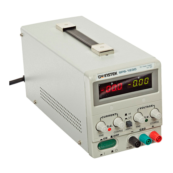
Page 15: Front Panel
5-1. Front panel CV Indicator Lights when the power is on and in constant voltage operation. CC Indicator Lights when in constant current operation. Voltage coarse For the coarse adjustment of the output voltage. Voltage fine For the fine adjustment of the output voltage. Current coarse For the coarse adjustment of the output current. - Page 16 Fig. 5-1 Front Panel...
- Page 17 Fig. 5-2 Rear Panel...
-
Page 18: Operation Instructions
6. OPERATION INSTRUCTIONS 6-1. Precaution (1) AC input AC input should be within the range of line voltage¡ Ó 15% 50/60Hz. WARNING: To avoid electrical shock, the power cord protective grounding conductor must be connected to ground. (2) Installation The machine itself is a heating source , please don't pile up the machine while operation. Keep the machine from other heating source at least for 10cm to assure a sufficient space for radiation in order to extend the life of the machine. - Page 19 (3) Output Current/Temperature Cure Line Chart: 100% Output Current Environment Temperature (¢ J )
- Page 20 (4) Output Test lead Selection: The Selection of Output Test Lead and Feedback Test Lead: For safety assurance, please select the adequate output test lead according to the following list: Conductor Maximum Permissible (CSA) Conductive Current Wire No. Component Cross Section Area Outer Model Resistor...
-
Page 21: Setting Current Limit
6-2. Setting Current Limit (1) Determine the maximum safe current for the device to be powered. (2) Temporarily short the (+) and (-) terminals of the power supply together with a test lead. (3) Rotate the COARSE VOLTAGE control away from zero sufficiently to have the CC indicator lightened. (4) Adjust the CURRENT control for the desired current limit. -
Page 22: Remote Error Sensing
C. Plug power cord into the power outlet. D. Set Power switch to “ON” position. E. Adjust “Voltage” and “Current” control to the desired output voltage and current. F. Connect the external load to the output binding posts. Make sure both “+” and “- ” terminals are connected correctly. - Page 23 The function of the Remote Error Sensing can only be applied to the Constant Voltage mode as shown in Figure 6-3. The feedback point of power supply must start from the load terminal directly. Therefore, the power supply can display its function on the load terminal instead of output terminal.
-
Page 24: Remote Control
6-6. Remote Control Short the Remote Control terminal for output ON, and open the Remote Control terminal for output OFF. 6-7. OVP Setting Firstly, adjust the OVP ADJ knob clockwise to the maximum OVP, then adjust output voltage to reach the voltage of OVP. Secondly, adjust the OVP ADJ knob counter-clockwise slowly until the OVP message appears. -
Page 25: Maintenance
7. MAINTENANCE The following instructions are used by qualified personnel only. To avoid electrical shock, do not perform any servicing other than the operating instructions of the manual unless you are qualified to do so. 7-1. Fuse Replacement If the fuse blown, the CV or CC indicators will not light and the power supply will not operate. The fuse should not normally blow unless a problem has developed in the unit. -
Page 26: Internal Adjustments
C. Adjust trimmer VR301 for a reading on the multi-meter to be 18.50V for SPS-1820, 36.50V for SPS-3610, and 60.50V for SPS-606, 24.5V for SPS-2415, 12.5V for SPS-1230. D. Adjust trimmer pot VR2 to set the reading value of voltmeter as same as the one shown on the multi-meter.. - Page 27 Fig. 7-1 Adjustment Location Fig. 7-2 Adjustment Location Fig. 7-3 Adjustment Location...
-
Page 28: Cleaning
7-4 Cleaning To clean the power supply, use a soft cloth dampened in a solution of mild detergent and water. Do not spray cleaner directly onto the instrument, since it may leak into the cabinet and cause damage. Do not use chemicals containing benzene, benzene, toluene, xylem, acetone, or similar solvents.
Need help?
Do you have a question about the SPS-1230 and is the answer not in the manual?
Questions and answers