Table of Contents
Advertisement
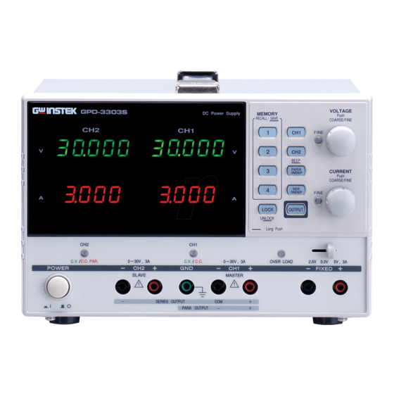
DC Power Supply
GPD-3303 Series
USER MANUAL
GW INSTEK PART NO.
ISO-9001 CERTIFIED MANUFACTURER
This manual contains proprietary information, which is protected by
copyrights. All rights are reserved. No part of this manual may be
photocopied, reproduced or translated to another language without
prior written consent of Good Will company.
The information in this manual was correct at the time of printing.
However, Good Will continues to improve products and reserves the
rights to change specification, equipment, and maintenance
procedures at any time without notice.
Good Will Instrument Co., Ltd.
No. 7-1, Jhongsing Rd., Tucheng City, Taipei County 236, Taiwan.
Advertisement
Table of Contents

Related Manuals for GW Instek GPD-3303 Series


Summary of Contents for GW Instek GPD-3303 Series
-
Page 1: Dc Power Supply
DC Power Supply GPD-3303 Series USER MANUAL GW INSTEK PART NO. This manual contains proprietary information, which is protected by copyrights. All rights are reserved. No part of this manual may be photocopied, reproduced or translated to another language without prior written consent of Good Will company. -
Page 2: Table Of Contents
TABLE OF CONTENTS GPD-3303 Series User Manual Error Messages ........2 7 H Table of Contents Command List........2 8 H Command Details ........ 2 9 H FAQ ................SAFETY INSTRUCTIONS ..........5 3 0 H OVERVIEW............... 9 APPENDIX .............. -
Page 3: Safety Instructions
• Measurement category III is for measurement performed in the Caution: Identifies conditions or practices that building installation. CAUTION could result in damage to the GPD-3303 series or • Measurement category II is for measurement performed on the to other properties. circuits directly connected to the low voltage installation. - Page 4 Make sure the cause of fuse blowout is fixed • Power cord for the United Kingdom before fuse replacement. When using the GPD-3303 series in the United Kingdom, make sure Disconnect the power cord before cleaning. Cleaning the • the power cord meets the following safety instructions.
-
Page 5: Overview
For a big load, the power supply can be used as a CV source; while for a small load, a This chapter describes the GPD-3303 series in a CC source. When in the CV mode (independent or nutshell, including its main features and front / tracking mode), output current (overload or short rear panel introduction. -
Page 6: Series Lineup / Main Features
OVERVIEW GPD-3303 Series User Manual Series Lineup / Main Features Principle of Operation Overview The power supply consists of the following. Series Lineup AC input circuit • Model V Meter A Meter USB Tracking Error Transformer • GPD-3303D 3 digit 3 digit Yes Bias power supply including rectifier, filter, ≤... -
Page 7: Front Panel Overview
OVERVIEW GPD-3303 Series User Manual The auxiliary rectifiers D1011~ D1014 provide bias Rectifier Front Panel Overview voltage filtered by the capacitors C102 and C103, for the pre-regulators U101 and U102. They provide a regulated voltage for other modules. The main rectifier is a full wave bridge rectifier. It... -
Page 9: Rear Panel Overview
(CC), according to load condition. When the current level is smaller than the output CV mode setting, the GPD-3303 series operates in Constant Voltage mode. The indicator on the front panel turns green (C.V.) The Voltage level is kept at the... -
Page 10: Setup
ETUP counterclockwise and loosen the screw. This chapter describes how to properly power up 2. Insert the cable terminal. and configure the GPD-3303 series before operation. 3. Turn the terminal clockwise and tighten the screw. Power Up Select AC voltage Before powering up the power Insert the plug into the socket. -
Page 11: Output On/Off
SETUP GPD-3303 Series User Manual Output On/Off Front Panel Lock Panel operation Pressing the Output key turns Panel operation Press the LOCK key to lock on all CH 1/2/3 outputs. the front panel key operation. The key LED The key LED also turns on. Pressing the Output key again turns the output and the key LED off. -
Page 12: Ch1/Ch2 Independent Mode
OPERATION GPD-3303 Series User Manual PERATION CH1/CH2 Independent Mode Note: this diagram shows non-European terminals. Background / CH1 and CH2 outputs work independent of each 3. Set the CH1 output voltage (For CH1) other. Connection and current. Press the CH1... -
Page 13: Ch3 Independent Mode
OPERATION GPD-3303 Series User Manual 3. To turn on the output, press CH3 Independent Mode the output key. The key LED turns on. Background / The CH3 rating is 2.5V/3.3V/5V, 3A fixed. It works independently from CH1 and CH2, Connection When the output Current level regardless of their modes. -
Page 14: Ch1/Ch2 Tracking Series Mode
CH1+ & CH2− (Single supply). Background Tracking series operation doubles the Voltage capacity of the GPD-3303 series by internally connecting CH1 (Master) and CH2 (Slave) in serial and combining the output to a single channel. CH1 (Master) controls the combined Voltage output level. - Page 15 OPERATION GPD-3303 Series User Manual 1. Press the SER/INDEP key to activate the tracking series mode. The key LED turns on. 2. Connect the load to the front panel terminals, CH1+ & CH2−. Use the CH1 (−) terminal as the common line connection.
-
Page 16: Ch1/Ch2 Tracking Parallel Mode
CH1/CH2 Tracking Parallel Mode status, refer to the CH1 meter and indicator. Background / Tracking parallel operation doubles the current capacity of the GPD-3303 series by internally Connection connecting CH1 and CH2 in parallel and combining the output to a single channel. CH1 controls the combined output. -
Page 17: Save/Recall Setup
OPERATION GPD-3303 Series User Manual 3. To turn on the output, press the output key. The key LED turns on. AVE/RECALL SETUP 4. The CH2 indicator turns red, indicating tracking parallel (PARA) mode. Save Setup 5. Press the CH1 key (LED... -
Page 18: Recall Setup
When a setting is recalled, the output Note Run this query command via the terminal Functionality automatically turns off. check application such as MTTTY (Multi-threaded TTY). *IDN? This should return the identification information: Manufacturer, model name, serial number, firmware version. GW INSTEK, GPD-3303x, SN: xxxxxxxx, Vx.xx... -
Page 19: Remote Connection Step
REMOTE CONTROL GPD-3303 Series User Manual Remote Connection Step Command Syntax Entering the 1. Connect the USB cable to the slave port. 1: command header Command format remote control mode 2: output channel 2. The connection will be automatically 3: separator established, and the front panel shows “USB…YES”... -
Page 20: Command List
REMOTE CONTROL GPD-3303 Series User Manual Command List Command Details Detailed descriptions of each command start from the next page. • The “HELP” command shows all the below commands and their • ISET<X>:<NR2> meanings, except for the HELP command itself. - Page 21 REMOTE CONTROL GPD-3303 Series User Manual VSET<X>? BEEP<Boolean> Description Returns the output voltage setting. Description Turns the beep on or off. Response time Minimum 80ms Panel operation See page21 Returns the CH1 voltage setting Minimum 70ms Example VSET1? Response time...
- Page 22 REMOTE CONTROL GPD-3303 Series User Manual Contents *IDN? ISET<x>:<NR2> Sets the value of current. Returns the GPD-3303D or GPD-3303S Description VSET<x>:<NR2> Sets the value of voltage. x:1=CH1,2=CH2. identification. ISET<x>? Return the value of current. Minimum 300ms Response time VSET<x>? Return the value of voltage.
-
Page 23: Faq
GPD-3303 Series User Manual PPENDIX Q1. I pressed the panel lock key but the output still turns on/off. F use Replacement 2 3 B A1. The output key is not affected by the panel lock key operation, for ensuring safety. -
Page 24: Specifications
A Meter GPD-3303D 3.2A full scale, 3 digits 0.5" LED 2 4 B The specifications apply when the GPD-3303 series are powered on display for at least 30 minutes under +20°C – +30°C. GPD-3303S 3.2A full scale, 4 digits 0.4" LED... -
Page 25: Declaration Of Conformity
APPENDIX GPD-3303 Series User Manual D eclaration of Conformity 2 5 B GOOD WILL INSTRUMENT CO., LTD. NDEX (1) No.7-1, Jhongsing Rd., Tucheng City, Taipei County, Taiwan (2) No. 69, Lu San Road, Suzhou City (Xin Qu), Jiangsu Sheng, China... -
Page 26: Index
INDEX overload indicator ....26 interface......36 power supply save settings safety instruction ....6 manual....... 34 setup ........19 remote........ 43 socket overview ....17 service operation specification.......48 about disassembly ..... 6 protective ground symbol ..5 contact ....... 45 rear panel overview .....17 status, instrument ....
Need help?
Do you have a question about the GPD-3303 Series and is the answer not in the manual?
Questions and answers