
Related Manuals for GW Instek GPP-3323


Summary of Contents for GW Instek GPP-3323
- Page 1 Programmable DC Power Supply GPP-1326/GPP-2323/GPP-3323/GPP-4323 User Manual ISO-9001 CERTIFIED MANUFACTURER...
- Page 2 Copyright Statement This manual contains proprietary information, which is protected by copyright. All rights are reserved. No part of this manual may be photocopied, reproduced or translated to another language without prior written consent of Good Will company. The information in this manual was correct at the time of printing. However, Good Will continues to improve products and reserves the rights to change specification, equipment, and maintenance procedures at any time without notice.
-
Page 3: Table Of Contents
Table of Contents Table of Contents SAFETY INSTRUCTIONS ..........6 Safety Symbols ............6 Safety Guidelines ............7 Power cord for the United Kingdom ......10 OVERVIEW ..............11 Introduction ............. 12 Key Features ............15 Front Panel .............. 17 Rear Panel.............. - Page 4 GPP Series User Manual Delay Function ............63 Set Delay Output ............. 63 Set Group Parameter ..........66 Menu Tree ..............68 Save and Recall ............71 Monitor Function ............. 73 Set Monitor .............. 74 Recorder Function ............ 76 Set Recorder ............. 77 Enternal I/O Control ..........
- Page 5 Table of Contents Output Commands ..........113 Source and Load Commands ........114 Status Commands ........... 119 System Commands ..........120 System Related Commands ........121 IEEE488.2 Common Commands ......121 Command Details ..........123 Measurement Commands ........123 Display Commands ..........125 Output Commands ..........
-
Page 6: Safety Instructions
GPP Series User Manual AFETY INSTRUCTIONS This chapter contains important safety instructions that you must follow during operation and storage. Read the following before any operation to insure your safety and to keep the instrument in the best possible condition. Safety Symbols These symbols may appear in the manual or on the instrument. -
Page 7: Safety Guidelines
SAFETY INSTRUCTIONS Safety Guidelines General Do not place any heavy object on the unit. Guideline Avoid severe impact or rough handling that leads to damaging the unit. CAUTION Do not discharge static electricity to the unit. Do not block the cooling fan opening. - Page 8 GPP Series User Manual Fuse Fuse type: 100V/120V:T6.3A/250V, 220V/230V:T3.15A/250V WARNING To prevent fire, replace the fuse only with the specified type and rating. Disconnect the power cord before replacing the fuse. Make sure the cause of fuse blowout is fixed before replacing the fuse.
- Page 9 SAFETY INSTRUCTIONS (Pollution Degree) EN 61010-1:2010 specifies pollution degrees and their requirements as follows. The GPP Series falls under degree 2. Pollution refers to “addition of foreign matter, solid, liquid, or gaseous (ionized gases), that may produce a reduction of dielectric strength or surface resistivity”.
-
Page 10: Power Cord For The United Kingdom
GPP Series User Manual Power cord for the United Kingdom When using the power supply in the United Kingdom, make sure the power cord meets the following safety instructions. NOTE: This lead/appliance must only be wired by competent persons WARNING: THIS APPLIANCE MUST BE EARTHED IMPORTANT: The wires in this lead are coloured in accordance with the following code: Green/ Yellow:... -
Page 11: Overview
OVERVIEW VERVIEW This chapter contains a brief introduction to GPP series including the main features and an overview of the front and rear panel. Use the Getting Started chapter on page 27 to start up instructions and how to setup the appropriate operation environment. -
Page 12: Introduction
The GPP-1326 has a 1 independent adjustable voltage outputs with sense.The GPP-2323 has a 2 independent adjustable voltage outputs. The GPP-3323 three independent outputs: two with adjustable voltage levels and one with fixed level selectable from 1.8V, 2.5V, 3.3V and 5V. The GPP-4323 has four independent voltage outputs that are all fully adjustable. - Page 13 OVERVIEW Load Mode The GPP series models have additional Load function on both CH1 & CH2 with 3 modes: CV (Constanct Voltage), CC (Constant Current) and CR (Constant Resistance), all of which can be selected through the function keys on the front panel.
- Page 14 GPP Series User Manual Display Change The GPP series provides up to 7 display types, Function each of which can be well selected via setting. For details, see page 32. Output Waveform Under Source mode of the GPP series, user can Function customize a certain V/I sequential waveform output.
-
Page 15: Key Features
Key Features Multiple Outputs: Features GPP-1326:32V/6A x 1 GPP-2323:32V/3A x 2 (CH1/CH2) GPP-3323:32V/3A x 2 (CH1/CH2) 1.8V/2.5V/3.3V/5V/5A x 1 (CH3) USB Port Output:3A GPP-4323:32V/3A x 2 (CH1/CH2) 5V/1A x 1 (CH3),15V/1A x 1 (CH4) Constant voltage and constant current operation (CV/CC). - Page 16 GPP Series User Manual Digital panel control. Operation Output on/off control (ON/OFF), and each channel can be controlled separately. Digital voltage and current settings. (Key & Encode) 10 groups of save/recall settings and 2 groups of power-on settings.
-
Page 17: Front Panel
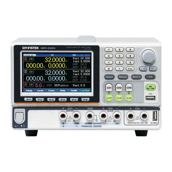
OVERVIEW Front Panel Number Scroll wheel/ Function Arrow keys keys Front panel Power button USB host output terminals *The panel above is the example of GPP-4323. For other models, refer to page 23. Display Display Interface (Take GPP-4323 model as example) - Page 18 GPP Series User Manual Channel Channel number and distribution vary by distribution models with different colors identifications: CH1: Yellow CH2: Blue CH3: Pink CH4: Green CH1 is master and CH2 becomes yellow under tracking series and tracking parallel modes. Single channel Channel/ Voltage Status...
- Page 19 CH3(GPP-3323) displays setting of voltage only Display OVP/OCP settings CH1/CH2/CH3/CH4: The CH3 OVP of GPP-3323 is a fixed value (approx. 5.5V), non-configurable and with only on or off switch available for user. OCP is available only for USB output port (approx.
- Page 20 GPP Series User Manual Status Display the set function/remote control interface Indicator : The active channel under setting status : The status of OTP protection mode : The status of USB flash drive connected : USB remotely disconnected : USB remotely connected : The status of control I/O connected Others: when operating in the series/parallel tracking mode, the corresponding SER/PAR icons...
- Page 21 OVERVIEW Number pad For parameter value setting Scroll wheel & Scroll wheel is used to set each Arrow keys parameter value, whilst arrow keys are used for parameter, menu selection and voltage/current fine adjustment. It is used to switch or operate the displayed waveforms under diagram display mode.
- Page 22 CH3 terminal Power output terminal Power output terminal (GPP- 3323 only) Warning: The output current from the 2 terminals should Not exceed 5A for GPP-3323. CH4 terminal Power output terminal GND terminal Ground terminal Voltage Sense terminal of power...
- Page 23 OVERVIEW Panels of other models: GPP-1326 GPP-2323 GPP-3323...
-
Page 24: Rear Panel
GPP Series User Manual Rear Panel Terminals Alternate AC voltage selection: input switch 100V/120V/220V/230V ±10%, frequency 50/60Hz AC input The AC input accepts socket and 100V/120V/220V/230V line fuse AC. The frequency is 50Hz/60Hz. Fuse: 100V/120V: T6.3A/250V, 220V/230V :T3.15A/250V, slow-blow type, See page 203 for details. - Page 25 OVERVIEW GPIB port GPIB slave port for remote control. Abides to IEEE488.2 (SCPI) protocol. See page 102 for details. LAN port LAN port for remote control. See page 103 for LAN setting and operation details. RS 232 port RS232 port for remote control.
-
Page 26: Constant Voltage/Constant Current Crossover Characteristics
GPP Series User Manual Constant Voltage/Constant Current Crossover Characteristics Background The unit will switch automatically between constant voltage and constant current according to changes in the load. CV mode When the load current is less than the current setting, the unit operates in constant voltage mode, changing the current level according to the load but maintaining the set voltage level until the current reaches the set current level. -
Page 27: Getting Started
GETTING STARTED ETTING STARTED This chapter describes the start up procedures and the preparation that is necessary before operating the power supply. Load Connection ............29 Turning the Output On/Off ........31... -
Page 28: Start Up
GPP Series User Manual Start Up Checking the AC Before the power is turned Voltage on, confirm that the input power supply meets the following conditions: 100V/120V/220V/230V ±10%,50/60Hz Connecting the The fuse is a slow-blow fuse. AC power cord 3.15A(220V/230V) 6.30A(100V/120V)... -
Page 29: Load Connection
GETTING STARTED Load Connection Recommended Model Specification Usage Cables GTL- Front panel terminal 104A GTL-105A Sense(1326 only) Front panel Use the GTL-104A cables for wiring the front panel source connections. USB Type A only (Greater than 4A) Use the GTL-105A cables for the GPP-1326 sense connections. - Page 30 GPP Series User Manual...
-
Page 31: Turning The Output On/Off
GETTING STARTED Turning the Output On/Off Panel Operation Press the Output key of each channel individually to turn the output on. The Output key will light-up when the output is on. When the output is turned on, pressing the Output key again will turn the output off. - Page 32 GPP Series User Manual ASIC OPERATION This chapter describes how to set various functions. Display Change ............33 Source Function ............36 Independent Output Mode ........41 Tracking Series and Tracking Parallel Modes ..43 Load Function ............46 Sequence Function ........... 50 Set Sequence Output ..........
-
Page 33: Basic Operation
BASIC OPERATION Display Change Display Area Channel/Status Work status area Read back status area Parameter setting area Function keys display area 1. Under the Source interface: Warning Each channel has its own setting area (V/I/OVP/OCP) and read back status area (V/I/W). 2. - Page 34 GPP Series User Manual Type GPP-1326 GPP-2323 GPP-3323 GPP-4323 Nomarl Type1 × Type2 × Type3 × × × Type4 Type5 Wave- Type6 form Type7 *Only Type 1, Type 4 and Type 7 have setting value display *Type's selection: Advance key ->F1(Display) key->F1(Normal) key or F2(Waveform) key.
- Page 35 BASIC OPERATION The introduction to Type 6 display a represents the currently edited channel, which can be toggled through the channel button on the panel. b indicates the adjustable items of reference point for voltage/current/power respectively in the active channel. The one with a red triangular arrow is the active item to adjust, which can be toggled through the directional button on the panel.
-
Page 36: Source Function
GPP Series User Manual Source Function Description Each channel is equipped with basic power functions and able to display both settings and read back value of V/I as well as output status Parameter Vset Set output voltage of active channel. description The range is as the following: CH1:0.000V-33.000V... - Page 37 BASIC OPERATION Set OCP. The range is as the following: CH1:0.05A - 3.50A CH2:0.05A - 3.50A CH3:0.05A - 1.20A (GPP-4323) CH4:0.05A - 1.20A (GPP-4323) Parameter Voltage Press the F1 key Setting (CH1 corresponding to for example) Voltage to activatate voltage setting area on LCD (red font color with the underline indicator).
- Page 38 GPP Series User Manual Current to activatate current setting area on LCD (red font color with the underline indicator). (a) Input digit with number pad (0- 9,.) and press unit key F1(A) or F2(mA) to confirm: Input 1.543V: (b) Step input: Press the left or right arrow buttons to select high and low level that...
- Page 39 BASIC OPERATION activated (red font color with the underline indicator). (a) Input digit with number pad (0- 9,.) and press unit key F1(V) or F2(mV) to confirm: Input 6.5V: (b) Step input: Press the left or right arrow buttons to select high and low level that require fine tune (underline...
- Page 40 GPP Series User Manual (red font color with the underline indicator). (a) Input digit with number pad (0- 9,.) and press unit key F1(A) or F2(mA) to confirm: Input 2.5A: CAUTION: There’s no proper sequence between turning on OVP/OCP functions and setting OVP/OCP value.
-
Page 41: Independent Output Mode
BASIC OPERATION current displays in red CC. OVP/OCP OVP/OCP displays in white when OVP is not in activation. OVP/OCP displays in red and output is off when OVP is activated. OVP/OCP displays in gray when OVP/OCP functions are off. Independent Output Mode Description Each channel within the models GPP- 1326/2323/3323/4323 series is apart from one... - Page 42 Load Voltage/Cur GPP-1326:32V/6A x 1 rent Rating GPP-2323/3323/4323: CH1/CH2: 32V/3A x 2 CH3:1.8V/2.5V/3.3V/5V/5A x 1 (GPP-3323) USB Port Output:3A (GPP-3323) 5V/1A x 1 (GPP-4323) CH4:15V/1A x 1 Setting 1. Press F4 or F5 button for operating the corresponding Independent to enter the Independent function.
-
Page 43: Tracking Series And Tracking Parallel Modes
BASIC OPERATION Tracking Series and Tracking Parallel Modes Descri Tracking series operation doubles the Voltage ption capacity of the GPP-2323/3323/4323 by internally connecting CH1 (Master) and CH2 (Slave) in series and combining the output to a single channel. CH1 (Master) controls the combined Voltage output level. Tracking series without common terminal Load Output... - Page 44 GPP Series User Manual current setting. 4. For setting operation of parameter, refer to page 37. Output The button ON/OFF of CH1/CH2 is individually available, while All ON/OFF button is available for all channels. Tracking series with common terminal Load Output 0 - 32V/0 - 3A for CH1+ - COM rating...
- Page 45 BASIC OPERATION Operation 1. Press F4 or F5 button for operating the corresponding Series to enter the tracking series function. Yellow SER will be shown on the status area. 2. Press CH1 button to proceed to CH1/CH2 voltage setting and CH1 limit current setting. 3.
-
Page 46: Load Function
GPP Series User Manual Output rating Rating 0 - 32V/0 - 6A Operation 1. Press F4 or F5 button for operating the corresponding Parallel to enter the tracking parallel function. Yellow PAR will be shown on the status area. 2. Press CH1 button to proceed to CH1/CH2 voltage/current setting. - Page 47 BASIC OPERATION Note The voltage (≥1V) or --.--- (<1V) pertaining to port appears when Output is Off. Parameter Load Under PWR. mode, press F6 (Load Description Mode) to enter the Load mode. LCD will display the status Vset Set rating range of voltage value under Load mode of active channel: CH1:1.50V-33.00V CH2:1.50V-33.00V...
- Page 48 GPP Series User Manual Others OPP: Fixed 50W of single channel(GPP-1326:100W), non- revisable OVP/OCP: indentical to Source Parameter Vset Press F4 or F5 button for operating setting the corresponding (CV) mode followed by F1 button (Vset). The voltage setting area on LCD will be activated and appears (red font color with the underline indicator).
- Page 49 BASIC OPERATION font color with the underline indicator). (a) number pad (0-9,.) input; press unit button F1 (A) or F2 (mA) button to confirm: Input 1.543A: (b) Step input: Press the left or right arrow buttons to select high and low level that require fine tune (underline below the corresponding number...
-
Page 50: Sequence Function
GPP Series User Manual (b) Step input: Press the left or right arrow buttons to select high and low level that require fine tune (underline below the corresponding number value), and scroll the scroll wheel to increase or decrease setting value. -
Page 51: Set Sequence Output
BASIC OPERATION are required to be output. Users can edit the output waveform according to their needs. The amplitude range of the output waveform is the output voltage range of power supply. The setting range for output waveform duration is 1s (duration calculation: Time x Groups x Cycles) and the resolution is 1s. - Page 52 GPP Series User Manual executed: output termination or being hold with the last step. Parameter Cycles Press the Advance key on control Setting panel. Select F2 (Sequence) function. Press F1 (Set) button followed by selecting F1 (Cycles). The setting on LCD is activated and appears in red font color .
-
Page 53: Set Group Parameter
BASIC OPERATION Under the Sequence function, press End State F1 (Set) button followed by selecting F4 (End State), and 2 statuses Last/Output off will appear in turn on LCD . The one displaying is what’s called the current status. Operation ON/OFF Press the F5 (SEQ.On) button. - Page 54 GPP Series User Manual Parameter Group number. Maximum 2047 Description Voltage Voltage setting of each group. Current Range: 0-33V Time Current setting of each group. Range: 0-3.2A Execution duration of each group. Range: 1S – 300S Parameter Under the Sequence function, press Setting F2 (Edit) button followed by selecting F1 (No.).
-
Page 55: Construct Templet
BASIC OPERATION Current Under the Sequence function, press F2 (Edit) button followed by selecting F4 (Current). The setting on LCD is activated and appears in red font color . Use number pad to set the parameters directly and then press the F1 (A) or F2 (mA) button to confirm;... - Page 56 GPP Series User Manual Exp Fall. Set the max. value of waveform Value voltage/current Set the min. value of waveform Value voltage/current Start Set the initial group number of waveform. Maximum: 2037 Points Select the required points. Range: 10- 2047 Inverted Invert the selected waveform Parameter...
- Page 57 BASIC OPERATION Press the F4 (Min Value) button. The Value setting on LCD will be activated and appears in red front color. Use number pad to set the parameters directly and then press the F1 (V/A) or the F2 (mV/mA) button to confirm;...
-
Page 58: Menu Tree
GPP Series User Manual the parameters directly and then press the F1 (Done) to confirm; or use arrow keys along with scroll wheel to complete the setting. Inverted Press the F4 (Inverted) button. On (inverted) and Off (non- inverted) appear on LCD in turn. - Page 59 BASIC OPERATION Advance Sequence Edit Templet Memory SEQ.On Return Cycles Object Type Restart Done Done Type *.CSV Sync Return PageUp Sine *.SEQ PageDown Pulse Return Ramp Start Time StairUp NewFile SEQ.Off Done Second More Return Last (Stair Dn) Save Return Next (Stair UpDn) Return...
-
Page 60: Save And Recall
GPP Series User Manual Save and Recall Description GPP models can save and recall the Sequence data from internal 10 groups or flash drive. Parameter Type Avaialble for *.CSV or *.SEQ Description file type New File Avaialble for creating new *.CSV or *.SEQ file type *.CSV or *.SEQ file type Save... - Page 61 BASIC OPERATION 3. Rotate the scroll wheel (Encode) to select target file. 4. Press F3 (Save) button to save the settings of Sequence into the Flash corresponding file. drive storage Press the F4 (Recall) button to recall the Sequence file of list to the current sequence settings when necessary.
- Page 62 GPP Series User Manual 5. Press F3 (Save) button to save the settings of Sequence into the corresponding file. 6. Press the F4 (Recall) button to recall the Sequence file of list to the current sequence settings when necessary.
-
Page 63: Delay Function
BASIC OPERATION Delay Function Description It is necessary to output a series of pulse in real applications. This function is available when voltage is constant. Output waveform can be edited per user’s preference. The amplitude range of the output waveform is the output voltage range of power supply. - Page 64 GPP Series User Manual Groups The number to be executed. It can NOT exceed 2048 for Start+Groups. There’re 3 statuses after the End State necessary Group and Cycle are executed: output termination or output on or being hold with the last step.
- Page 65 BASIC OPERATION Groups Under the Delay function, press the F1 (Set) button followed by selecting the F3 (Groups), the setting on LDC will be activated and appears in red font . Use number pad for direct setting followed by pressing F1 (Done) key to confirm; or use arrow keys along with scroll wheel to complete setting.
-
Page 66: Set Group Parameter
GPP Series User Manual perform the function of closing Delay . In Delay ON, the F1 (Restart) button appears, it means that start from the first; in CH1/CH2 running delay, the F2 (Sync) button appears, it means that two channels start from the first at the same time. - Page 67 BASIC OPERATION (Decline). Base Time is for setting time of initial Group. Step is for setting time interval of neighboring Group. Parameter Under the Delay function, press the Setting F2 (Edit) button followed by selecting the F1 (No.). The setting on LCD is activated and appears in red font color .
-
Page 68: Menu Tree
GPP Series User Manual Patterm Under the Delay function, press the F2 (Edit) button followed by selecting F4 (Pattern), and then set up via F1 (01Patt) and F2 (10Patt). The live setting result appears on the LCD. Time Set Under the Delay function, press the F2 (Edit) button followed by selecting the F5 (Time Set), and then set time change patterns of each... - Page 69 BASIC OPERATION Description User is able to well understand the overall functions of Delay via menu tree, which is put in proper order by layer. The Return key is used for back to the parent menu. See the construction below: Level1------------ Advance Level2------------ Delay Level3------...
- Page 70 GPP Series User Manual Advance Delay Edit Stop Memory Delay On Return Cycles None Type Restart Done Done Voltage *.CSV Sync Return PageUp Define *.DLY PageDown Delay.Off Return Start State Return NewFile Return Done Return Current Save Inverted Define Last Recall Next Return...
-
Page 71: Save And Recall
BASIC OPERATION Save and Recall Description GPP models can save and recall the Delay data from internal 10 groups or flash drive. Parameter Type Avaialble for *.CSV or *.DLY file type Description New File Avaialble for creating new *.CSV or *.DLY file type Save Save the delay data to the specified... - Page 72 GPP Series User Manual 3. Rotate the scroll wheel (Encode) to select target file. 4. Press F3 (Save) button to save the settings of Delay into the corresponding file. 5. Press the F4 (Recall) button to recall the Delay file of list to the current Flash sequence settings when necessary.
-
Page 73: Monitor Function
In order to have well understanding of the channel under long-term output, the GPP series has the additional live monitor function, which helps guarantee load status of client via halting operation based on certain preset conditions. Warning: this feature is Not applicable to CH3 of GPP-3323. -
Page 74: Set Monitor
GPP Series User Manual Set Monitor Parameter Voltage Set condition of monitor of voltage. Description Current Set condition of monitor of current. Power Set condition of monitor of power. Stop Set status after halt. 3 types are Type available, output disable, content notice and audible alarm. - Page 75 BASIC OPERATION Current Press the Advance key on control panel. Select the F4 (Monitor) function followed by pressing the F2 (Current) button to enter the current setting. 1. Press the F1 (Set) button. The setting on LCD is activated and appears in red font color.
-
Page 76: Recorder Function
In order to have well understanding of the channel under long-term output, the GPP series has the additional live record function, which saves file via media for further analysis later. Warning: this feature is Not applicable to CH3 of GPP-3323. -
Page 77: Set Recorder
BASIC OPERATION Set Recorder Parameter Period Set period of each recorded. Description Groups Set recorded group number. Channel Set recorded channel. Memory Set saving location of record. Parameter Period Press the Advance key on control Setting panel. Select F5 (Recorder) function. Press F1 (Period) button to enter setting of recorded period. - Page 78 GPP Series User Manual group number. The setting on LCD is activated and appears in red font color. Use number pad to set the parameters directly and then press the F1 (Done) button to confirm; or use arrow keys along with scroll wheel to complete the setting.
- Page 79 BASIC OPERATION Press F3 (Save) button to save the temporary data into the corresponding file. Press F4 (Recall) button to save the record data of file into the temporary storage for further saving into flash drive later. Flash Type/*.CSV/ *.REC/New drive File/Select buttons appear when operation...
-
Page 80: Enternal I/O Control
GPP Series User Manual Enternal I/O Control Description The GPP series models provides user with a programmable external trigger port, which is used to dock certain functions control. Function It can turn each Data Line (D0,D1,D2,D3,D4) into input signal respectively to have command of the following four functions: 1. - Page 81 BASIC OPERATION Rear Pannel Up to 10 terminals within Control Port the control port; the upper 5 terminals can be set input/output functions, while the lower 5 are ground terminals. See diagram in right side for details (rear view). Schematic diagram The control circuit of each port is illustrated for control signal as the diagram below (D1 for example)
-
Page 82: Key Function Description
GPP Series User Manual Key Function Description Input/Output Mode: Function Operation Result Data Line Select object to be set from D0 to F4 Enable Set to Enable or Disable function of the port Mode Set which mode to adopt: Input Mode or Output Mode Channel Select corresponding channel: F1(CH1), F2... - Page 83 BASIC OPERATION F5 (More) under Output Mode setting: Function Operation Result Condition Set response type: F1(Output), F2 (Voltage), F3 (Current), F4 (Power), F5 (Auto) Note: F5 (Auto) triggers automatically only when voltage, current or power triggers meet at least one condition. Polarity Set the polarity of output signal F3,F4...
- Page 84 GPP Series User Manual ILE OPERATION Restore Factory Default Settings ......88...
-
Page 85: File Operation
FILE OPERATION Save/Recall Description System provides user with 4 different files, each of which has 10 groups including parameter setting *.set, use record *.rec, sequence output *.seq and delay output *.dly. Note: Both file folder and name in flash drive are limited within 8 characters. - Page 86 GPP Series User Manual Press the right arrow button to enter the file group. Rotate the scroll wheel (Encode) and stop at the file in need Press the F3 (Save) button to have the settings of current model saved into the corresponding file. Or press the F4 (Recall) button to recall the corresponding file, whose file name will be shown on the status bar.
- Page 87 FILE OPERATION Recorded Refer to page 79 for chapter of Memory operation of file Record. operation *.REC Note: *.REC file can be edited in PC by the specified format (*.CSV or *.REC) and imported, via flash drive, into PC. In the System Setting menu, the interface parameter settings area shows Power On.
-
Page 88: Restore Factory Default Settings
GPP Series User Manual Restore Factory Default Settings There’s a group of Default value, the non- Description modifiable factory default setting. User is able to restore Default or proceed to Preset operation from Power On under System. Operation Press the System button to enter the interface followed by pressing either the F2 (Power On) or the F5 (Preset) button to select Default. -
Page 89: System Settings
GPP Series User Manual YSTEM SETTINGS System Information ..........90 System Settings ............91 Firmware Upgrading ..........93 Description of Using Flash Drive ......94... -
Page 90: System Information
GPP Series User Manual System Information System The picture below shows complete system Information information. If the selected model is without ports (GPIB, LAN), the corresponding info will disappear. GPIB Check Press the System button on the panel to show the operation screen as above. -
Page 91: System Settings
SYSTEM SETTINGS System Settings Description It can be used to perform system operations for machine. Setting Interface Remote control and relevant information data output setting Power On Power on initial state setting Language menu language setting BackLight Adjust the LCD brightness. Beeper Sets when the buzzer is turn on. - Page 92 GPP Series User Manual Backlight In the System menu, press the F3 (Setting) brightness button followed by selecting the F2 (Backlight) adjustment to adjust backlight brightness. There are three brightness levels: High, Middle, and Low. Select from pressing the F1 (Low) or F2 (Middle) or F3 (High) button.
-
Page 93: Firmware Upgrading
SYSTEM SETTINGS Firmware Upgrading When to When system is failure, request by customer GW Upgrade Instek. When the system fails, firmware can Firmware requested by GW Instek customers. Upgrade Firmware file Supplied by Requirement GW Instek Operation After plugging in flash drive, the corresponding symbol appears in the status bar. -
Page 94: Description Of Using Flash Drive
GPP Series User Manual Description of Using Flash Drive Description It can be used when upgrading the software upgrades, screenshot operation and importing or exporting files. Flash drive only support USB2.0/USB3.0,FAT32 file system,16G MAX. Operation Insert flash driver into the USB Host port. Then the system identifies the flash driver and the indentification appears in the status bar. - Page 95 SYSTEM SETTINGS Exporting the The files of Sequence (*.SEQ), Recorder Sequence data (*.REC), Delay (*.DLY), etc within machine can be, in addition to individual format, converted to *.CSV file format for easy check and edit in PC by user. For more details, refer to page 85.
-
Page 96: Remote Control
REMOTE CONTROL EMOTE CONTROL RS-232 ..............99 USB ................100 GPIB ................. 102 LAN ................103 Command Syntax ........... 109 Command List ............113 Measurement Instructions ........113 Display Functions ............ 113 Output Commands ..........113 Source and Load Commands ........114 Status Commands ........... - Page 97 REMOTE CONTROL Enable Registers ............192 Status Byte Register ..........192 Standard Event Register .......... 194 Status Byte Register Commands......195 Standard Event Register Commands ...... 196 Other Status Register Commands ......198 Errors ..............199 Error Message ............199 Command Errors .............
-
Page 98: Connection Usage
GPP Series User Manual Connection Usage This chapter describes how to set and enable port, as well as all the required preparations prior to operation. Port type The GPP series has 2 standard remote control ports (RS-232, USB), and 2 optional ports (GPIB, LAN). - Page 99 REMOTE CONTROL RS-232 Description The GPP series models can be remotely controlled by RS-232 connection. Interface Rear panel RS-232 port Connection Under power-off state, connect RS-232 cable and select RS-232 port in the Interface. The message USB232 will appear gray in the status bar when connection, and turns to white color while the first command connects succesfully.
-
Page 100: Usb
GPP Series User Manual Function check Perform the following query: *IDN? The unit will return the manufacturer, model, serial number and software version. GW INSTEK, GPP-3323, SN: xxxxxxxx, Vx.xx Disable Remote Control Mode Send a remote command Local from the PC. ... - Page 101 Function Check Perform the following query: *IDN? The unit will return the manufacturer, model, serial number and software version. GW INSTEK, GPP-2323, SN: xxxxxxxxx, Vx.xx Send a remote command from the PC Disabling Remote Long-press the F6 (unlock) key on the front Control Mode panel.
-
Page 102: Gpib
GPP Series User Manual GPIB Description The communication data format, compatibility settings and GPIB address must all be configured before using GPIB remote control. Interface Rear panel GPIB port. Connection Select GPIB port in the Interface after connecting the GPIB cable. The message GPIB will appear gray in the status bar when connection, and turns to white... -
Page 103: Lan
REMOTE CONTROL Description When using the LAN port, the relevant parameters are supposed to be set earlier. Connection Select LAN port in the Interface after connecting the LAN cable. The message LAN will appear gray in the status bar when connection, and turns to white color while the first command connects succesfully. - Page 104 GPP Series User Manual D. press the F4 (Host Name) button to manually input. The Name area will be activated and become red color after setting. The default first letter is A, and can be changed to other string by rotating scroll wheel Encoder (A, B...Z, a, b...z, 1, 2...9, 0, - in clockwise sequence).
- Page 105 REMOTE CONTROL Manual IP A. Press the System button to enter the system interface followed by pressing the F1 (Interface) button to configure port parameter. B. Press the F4 (LAN) button to configure internet port parameter. C. Press the F2 (Config) button to configure relevant parameter.
- Page 106 GPP Series User Manual Parameter Settings: IP Address: IP address range: 1.0.0.0 to 223.255.255.255 (excluding 127.nnn.nnn.nnn). Subnet Mask: Subnet Mask Range: 1.0.0.0 to 255.255.255.255. Gateway: Gateway range: 1.0.0.0 to 223.255.255.255 (excluding 127.nnn.nnn.nnn). VISA Resource name: TCPIP0::169.254.129.17::1026::SOCKET DHCP A. Press the System button to enter the system interface followed by pressing the F1 (Interface) button to configure port parameter.
- Page 107 REMOTE CONTROL PC Operation 1. Enter the IP address into Microsoft Internet Explorer (IE). After entering the IP address you will be shown the Welcome screen which displays the instrument information. The page also provides three links: Welcome Page, Browser Web Control and View & Modify Configuration (network settings).
- Page 108 GPP Series User Manual 4. Click “Modify Config” to enter the network configuration setting menu, as shown below. Use the mouse to click on “Save and Restart” to change the remote settings for the GPP series. Click “Undo Edits” to cancel all the edited Note settings.
-
Page 109: Command Syntax
REMOTE CONTROL Command Syntax The commands that are used with the GPP series meet IEEE488.2 and SCPI standards. SCPI Commands Overview SCPI Command Format SCPI is an ASCII based command language designed for test and measurement instruments. SCPI commands uses a hierarchical structure (tree system), and is divided into different subsystems. - Page 110 GPP Series User Manual Symbol Description SCPI commands have the following conventional symbols. These symbols are not commands but are used to describe the command parameters. 1. Curly Brackets { } Curly Bracket enclose command string parameters, for example: {OFF|ON} 2.
- Page 111 REMOTE CONTROL Parameter Types The commands have a number of different parameter categories. How the parameters are set depend on the parameter categories. 1. Boolean Commands parameter that have to states “OFF” and “ON”, for example, DISPlay:FOCUs {ON|OFF}. “ON” will turn on the focus display function, while “OFF”...
- Page 112 GPP Series User Manual 5. ASCII Strings ASCII string parameters must use a combination of ASCII characters in a string. For example: For the command: MODE <name>, <name> must be an ASCII string. Command Abbreviations The syntax for SCPI commands contains a combination of upper and lower case letters.
-
Page 113: Command List
REMOTE CONTROL Command List Measurement Instructions :MEASure[1|2|3|4]:<function>? Page 123 Page 123 :MEASure[1|2|3|4]:ALL? Page 123 :MEASure:<function>:ALL? Page 124 VOUT<X>? IOUT<X>? Page 124 Display Functions Page 125 :DISPlay:ENABle <b> Page 125 :DISPlay:ENABle? Page 125 :DISPlay:BRIGhtness <NRf> :DISPlay:BRIGhtness? Page 125 Page 125 :DISPlay:TYPE {1|2|3|4|5|6|7} Page 126 :DISPlay:TYPE? Output Commands... -
Page 114: Source And Load Commands
GPP Series User Manual Page 129 :OUTPut[1|2|3|4]:OCP:STATe <b> Page 129 :OUTPut[1|2|3|4]:OCP:STATe? Page 129 :OUTPut[1|2|3|4]:OCP:TRIGger? :OUTPut[1|2|3|4]:OCP <value> Page 130 Page 130 :OUTPut[1|2|3|4]:OCP? Source and Load Commands Page 131 :SOURce[1|2|3|4]:CURRent <NRf> Page 131 ISET<X>:<NR2> :SOURce[1|2|3|4]:CURRent? Page 131 Page 131 ISET<X>? Page 132 :SOURce[1|2|3|4]:CURRent[:LIMit]:STATe? Page 132 :SOURce[1|2|3|4]:VOLTage <NRf>... - Page 115 REMOTE CONTROL Page 137 :LOAD:DISPlay {Low|Middle|High} Page 137 :LOAD:DISPlay? Page 137 :DELAy[1|2]:CYCLEs {N|I}[,<value>] :DELAy[1|2]:CYCLEs? Page 138 Page 138 :DELAy[1|2]: ENDState {ON|OFF|LAST} Page 138 :DELAy[1|2]: ENDState? Page 138 :DELAy[1|2]:GROUPs <NRf> :DELAy[1|2]:GROUPs? Page 139 :DELAy[1|2]:PARAmeter <No>,{ON|OFF},<time> Page 139 Page 139 :DELAy[1|2]:PARAmeter? <No>,<cecount> Page 140 :DELAy[1|2]: RESTart :DELAy[1|2]:STARt <value>...
- Page 116 GPP Series User Manual {AND|OR|NONE} Page 147 :MONItor[1|2|3|4]:CURRent:CONDition? Page 147 :MONItor[1|2|3|4]:CURRent[:VALue] {<value>|MINimum|MAXimum} :MONItor[1|2|3|4]:CURRent[:VALue]? Page 147 :MONItor[1|2|3|4]:POWER:CONDition {<P|>P|=P|NONE} Page 147 Page 148 :MONItor[1|2|3|4]:POWER:CONDition? Page 148 :MONItor[1|2|3|4]:POWER[:VALue] {<value>|MINimum|MAXimum} Page 148 :MONItor[1|2|3|4]:POWER[:VALue]? Page 149 :MONItor[1|2|3|4][:STATe] {ON|OFF} :MONItor[1|2|3|4][:STATe]? Page 149 Page 149 :MONItor[1|2|3|4]:STOPway {OUTOFF| ALARM |BEEPER},{ON|OFF} Page 149 :MONItor[1|2|3|4]:STOPway?
- Page 117 REMOTE CONTROL Page 153 :RECOrder[1|2|3|4]:ENABle? Page 154 :SEQUence[1|2]:CYCLEs {N|I}[,<value>] Page 154 :SEQUence[1|2]:CYCLEs? :SEQUence[1|2]:ENDState {OFF|LAST} Page 154 Page 155 :SEQUence[1|2]:ENDState? Page 155 :SEQUence[1|2]:GROUPs <value> Page 155 :SEQUence[1|2]:GROUPs? :SEQUence[1|2]:PARAmeter <No>,<volt>,<curr>,<time> Page 155 :SEQUence[1|2]:PARAmeter? <No>,<count> Page 156 Page 157 :SEQUence[1|2]:RESTart Page 157 :SEQUence[1|2]:STARt <value> :SEQUence[1|2]:STARt? Page 157 :SEQUence[1|2][:STATe] {ON|OFF}...
- Page 118 GPP Series User Manual Page 161 :SEQUence[1|2]:TEMPlet:OBJect? Page 162 :SEQUence[1|2]:TEMPlet:POINTs <value> Page 162 :SEQUence[1|2]:TEMPlet:POINTs? :SEQUence[1|2]:TEMPlet:RISERate <value> Page 162 Page 162 :SEQUence[1|2]:TEMPlet:RISERate? Page 163 :SEQUence[1|2]:TEMPlet:SELect {SINE|PULSE|RAMP|UP|DN|UPDN|RISE|FALL} Page 163 :SEQUence[1|2]:TEMPlet:SELect? :SEQUence[1|2]:TEMPlet:SYMMetry <value> Page 163 :SEQUence[1|2]:TEMPlet:SYMMetry? Page 163 :SEQUence[1|2]:TEMPlet:WIDTh <value> Page 163 Page 164 :SEQUence[1|2]:TEMPlet:WIDTh? :SEQUence[1|2]:TEMPlet:STARt <value>...
-
Page 119: Status Commands
REMOTE CONTROL {D0|D1|D2|D3|D4},]{RISE|FALL|HIGH|LOW|STATE } Page 170 :TRIGger:IN:TYPE? {D0|D1|D2|D3|D4} Page 170 :TRIGger:OUT:CONDition {D0|D1|D2|D3|D4},{OUTOFF|OUTON|>V|<V|=V|>C|<C|=C| >P|<P|=P|AUTO} ,<value> Page 172 :TRIGger:OUT:CONDition? {D0|D1|D2|D3|D4} :TRIGger:OUT[:ENABle] {D0|D1|D2|D3|D4},{ON|OFF} Page 172 :TRIGger:OUT[:ENABle]? {D0|D1|D2|D3|D4} Page 172 Page 172 :TRIGger:OUT:POLArity {D0|D1|D2|D3|D4},{POSItive|NEGAtive} Page 173 :TRIGger:OUT:POLArity? {D0|D1|D2|D3|D4} Page 173 :TRIGger:OUT:SOURce {D0|D1|D2|D3|D4},{CH1|CH2|CH3|CH4} Page 173 :TRIGger:OUT:SOURce? {D0|D1|D2|D3|D4} :TRIGger:OUT:STATe [D0|D1|D2|D3|D4,] {ON|OFF} Page 174... -
Page 120: System Commands
GPP Series User Manual Page 177 :STATus:QUEStionable:ENABle <NRf> Page 178 :STATus:QUEStionable:ENABle? Page 178 :STATus:QUEue[:NEXT]? :STATus:QUEue:ENABle <list> Page 178 Page 179 :STATus:QUEue:ENABle? Page 179 :STATus:QUEue:DISable <list> Page 179 :STATus:QUEue:DISable? :STATus:QUEue:CLEar Page 179 System Commands Page 180 :SYSTem:VERSion? Page 180 :SYSTem:ERRor? Page 180 ERR? :SYSTem:CLEar Page 181... -
Page 121: System Related Commands
REMOTE CONTROL Page 184 :SYSTem:BEEPer:STATe {0|1|OFF|ON} Page 185 BEEP<Boolean> Page 185 :SYSTem:BEEPer:STATe? :SYSTem:LOCal Page 185 Page 185 LOCAL Page 185 :SYSTem:INTerface [USB|RS232|GPIB|LAN] Page 186 :SYSTem:LANGuage [CHINese|ENGlish] :SYSTem:LANGuage? Page 186 :SYSTem:BAUDrate:USB [9600|19200|38400|57600|115200] Page 186 Page 186 :SYSTem:BAUDrate:USB? Page 186 :SYSTem:BAUDrate:RS232 [9600|19200|38400|57600|115200] Page 186 :SYSTem:BAUDrate:RS232? Page 187... - Page 122 GPP Series User Manual Page 196 *ESE? Page 196 *ESR? Page 198 *CLS *OPC Page 198 Page 198 *OPC?
-
Page 123: Command Details
<function> CURRent[:DC]:Measures the current. VOLTage[:DC]:Measures the voltage. POWEr[:DC]:Measures the power. Example :MEASure2:CURRent? Reads back the CH2 current value. About CH3 of GPP-3323, The query voltage will Note return the set value, current and power will return zero. Command :MEASure[1|2|3|4]:ALL? Function... - Page 124 Returns the actual output voltage. Description 1= CH1, 2= CH2, (4323: 3= CH3, 4=CH4) Example VOUT1? Returns the CH1 output voltage About CH3 of GPP-3323, The query voltage will Note return the set value. IOUT<X>? Command Function Returns the actual output current.
-
Page 125: Display Commands
REMOTE CONTROL Display Commands Command :DISPlay:ENABle <b> Function Turn the LCD display on or off. Description 0/OFF: Turns the display off. 1/ON: Turns the display on. Example :DISPlay:ENABle ON Turns the LCD display on. Command :DISPlay:ENABle? Function Queries the state of the display. Example :DISPlay:ENABle? Returns the state of the display. - Page 126 GPP Series User Manual Function Sets the display screens. For details, see page 33. Example :DISPlay:TYPE 4 Sets the display screens of TYPE4. Command :DISPlay:TYPE? Function Queries the TYPE of display screens. Example :DISPlay:TYPE? Returns the TYPE of display screens.
-
Page 127: Output Commands
REMOTE CONTROL Output Commands Command :OUTPut[1|2|3|4][:STATe] <b> Function Turns the output on or off. Description <b> 0/OFF: Turn off the output 1/ON: Turn on the output Example :OUTPut:STATe ON Turns on the output. of CH1 Command :OUTPut[1|2|3|4][:STATe]? Function Queries the output state. Example :OUTPut:STATe? Returns the output state of CH1. - Page 128 GPP Series User Manual Example OUT1 Turns on the output Command :OUTPut[1|2|3|4]:OVP:STATe <b> Function Turns OVP protection on/off Description <b> 0/OFF:Turns OVP off. 1/ON:Turns OVP on. Example :OUTPut2:OVP:STATe ON Turn on OVP on CH2. Command :OUTPut[1|2|3|4]:OVP:STATe? Function Queries the status of the OVP function. Example :OUTPut2:OVP:STATe? Returns the status of the OVP function on CH2.
- Page 129 REMOTE CONTROL About CH3 of GPP-3323, The OVP value can not be Note set. Command :OUTPut[1|2|3|4]:OVP? Function Queries the OVP voltage level. Example :OUTPut2:OVP? Queries the OVP voltage level on CH2. About CH3 of GPP-3323, OVP query value is 5.5V.
- Page 130 Refer to the specification sheet on page 200 for value Example :OUTPut2:OCP 1.5 Sets the OCP voltage to 1.5A for CH2. The USB port of GPP-3323, OCP value can not be Note set. :OUTPut[1|2|3|4]:OCP? Command Queries the OCP current level.
-
Page 131: Source And Load Commands
Description <NRf> specification sheet on page 198 for MAX value) Example :SOURce2:CURRent 1.0005 Sets the current level to 1.0005A for CH2. About CH3 of GPP-3323, The current value can not Note be set. Command ISET<X>:<NR2> Function Sets the current level. - Page 132 0.000-MAX Example :SOURce2:VOLTage 5.321 Sets the output voltage to 5.321V for CH2. About CH3 of GPP-3323, If the settings are not Note 1.8V/ 2.5V/3.3V or 5V, the existing output will not be affected and errors message will occur, Please refer to ":SYSTem:ERRor?"...
- Page 133 REMOTE CONTROL About CH3 of GPP-3323, Please refer to Note ":SOURce[1|2|3|4]:VOLTage < NRf >" Command :SOURce[1|2|3|4]:VOLTage? Function Queries the output voltage setting. Example :SOURce2:VOLTage? Queries the output voltage setting on CH2. Command VSET<X>? Function Returns the output voltage setting. X :1= CH1, 2= CH2, (4323: 3 = CH3, 4= CH4)
- Page 134 Function Queries the setting current value in all channnels. Example :SOURce:CURRent:ALL? Queries the setting current value and returns the readback value for all channels. About CH3 of GPP-3323, current value will returns Note 5.0000A. Command :SOURce:VOLTage:ALL? Function Queries the setting voltage value in all channnels.
- Page 135 REMOTE CONTROL [FAST]: In order to protect the function switching Description device” relay”, it is necessary to wait until the voltage and current drop to zero under normal conditions. When FAST is enabled, this factor will not be considered, but it is easy to damage the “relay”, so it is recommended to use it with caution.
- Page 136 GPP Series User Manual [FAST]: In order to protect the function switching Description device” relay”, it is necessary to wait until the voltage and current drop to zero under normal conditions. When FAST is enabled, this factor will not be considered, but it is easy to damage the “relay”, so it is recommended to use it with caution.
- Page 137 REMOTE CONTROL Function Queries the Load CR level. Description <NRf> 1-1000 Example : LOAD2: RESistor? Return the Load CR level for CH2. Command :LOAD:DISPlay {Low|Middle|High} Function In load mode, set the minimum voltage value that be displayed. The factory default is high. Below this value, it will display --.---- Description Low: 0.5V;Middle: 0.75V;High:1V...
- Page 138 GPP Series User Manual Command :DELAy[1|2]:CYCLEs? Function Queries the cycle number of Delay. Example :DELAy2:CYCLEs? Return to I or N, <value> for CH2 (For example: N,100) Command :DELAy[1|2]: ENDState {ON|OFF|LAST} Function Sets the termination state of Delay. Description ON|OFF|LAST ON: output enabled OFF: output disabled LAST: stay at the last group of output state.
- Page 139 REMOTE CONTROL Example :DELAy2:GROUPs 100 Sets the output number of Delay as 100 for CH2. Command :DELAy[1|2]:GROUPs? Function Queries the output number of Delay. Example :DELAy2:GROUPs? Return the output number of Delay for CH2. Command :DELAy[1|2]:PARAmeter <No>,{ON|OFF},<time> Function Sets the delay parameter of Delay. <No>...
- Page 140 GPP Series User Manual Function Queries the delay parameter of the specified groups of Delay. Returns to a string initiating from #. Data head is to describe data length information starting from #. For example, ##9000000017, the later 9 digits (000000017) following the initial 9 indicate length of data flow (17 bytes).
- Page 141 REMOTE CONTROL :DELAy[1|2]:STARt? Command Queries the sequence number for initial execution of Function the channel delay output. Example :DELAy2:STARt? Returns the initial sequence number of CH2 sequence output. Command :DELAy[1|2][:STATe] {ON|OFF} Function Enable or disable the delay output function of the active channel.
- Page 142 GPP Series User Manual Example :DELAy2:STATe:GENE 01P The automatically generated state will repeat by the sequence of Off and the On for CH2. Command :DELAy[1|2]:STATe: GENErate? Queries the currently used pattern of the Function automatically generated state. Example :DELAy2:STATe:GENE? Queries the currently used pattern of the automatically generated state for CH2.
- Page 143 REMOTE CONTROL Example :DELAy2:STOP? Queries the current stop condition, back to NONE or stop condition value. Command :DELAy: SYNChronize {ON|OFF} When both CH1 and CH2 are Delay on, turn on or Function off the delay synchronization between them Example :DELAy: SYNChronize ON turn on the delay synchronization of CH1 and CH2.
- Page 144 GPP Series User Manual <value0> The duration of “ON” state. Description <value1> The duration of “OFF” state. FIX (fixed time) sets <value0> and <value1> time, which ragne from 1s to 300s. The default setting of delay time is enabled when only a time parameter is specified.
- Page 145 REMOTE CONTROL Example :DELAy2:TIME:GENE? Queries the CH2 method of automatically generated time for delay and the corresponding parameter. Return a string with format consisting of the method of automatically generated time, <value0>,<value1>. Command :DELAy[1|2]:MEMory:SAVE {0|1|2|3|4|5|6|7|8|9} Saves the delayed file to the designated location of Function internal storage.
- Page 146 GPP Series User Manual Parameter <dest> indicates the designated location of external storage with file format in either usb:\<name>.CSV or usb:\<name>.DLY. The file name spans up to the max. 8 alphanumeric characters. .CSV/.DLY represents the suffix of file name. Storage location can not be designated when delay function is enabled.
- Page 147 REMOTE CONTROL Example :MONItor2:CURRent:CONDition <C,AND Sets the CH2current monitor condition for monitor as <current, and the logical pattern as “and”. Command :MONItor[1|2|3|4]:CURRent:CONDition? Queries the current monitor condition for monitor Function (active channel). Example :MONItor2:CURRent:CONDition? Queries the CH2 current monitor condition for monitor.
- Page 148 GPP Series User Manual Function Sets the power monitor condition for monitor (active channel). Description {<P|>P|NONE} Sets power monitor condition as “ <P”(<power),“ >P”(>power) , “=P”(=power)or “NONE”(none-monitored power) Example : MONItor2:POWER: CONDition <P Sets the CH2 power monitor condition of monitor as <power.
- Page 149 REMOTE CONTROL Command :MONItor[1|2|3|4] [:STATe] {ON|OFF} Function Enable or disable monitor (active channel) Example :MONItor2 ON Enable monitor for CH2 Command :MONItor[1|2|3|4][:STATe]? Function Queries whether the current monitor is On or Off (active channel). Example :MONItor2? Queries whether the current monitor is On or Off of CH2.
- Page 150 GPP Series User Manual Command :MONItor[1|2|3|4]:VOLTage:CONDition{<V|>V |=V|NONE},{AND|OR|NONE} Function Queries the voltage monitor condition of monitor (active channel). Description {<V|>V|=V|NONE} Sets voltage monitor condition as “ <V”(<voltage),“ >V”(>voltage) , “=V”(=voltage)or “ NONE”(none-monitored voltage) {AND|OR|NONE} Practical monitor condition is the logical composition of voltage, current and power.
- Page 151 REMOTE CONTROL Command :MONItor[1|2|3|4]:VOLTage[:VALue]? Function Queries the voltage monitor value of monitor (active channel). Example :MONItor2:VOLTage? Queries the CH2voltage monitor value for the current monitor. Command :RECOrder[1|2|3|4]:PATH? Function Queries the save location of recorded file. Example :RECOrder2:PATH? Queries the save location of recorded file for CH2. Command :RECOrder[1|2|3|4]:MEMory{0|1|2|3|4|5|6|7|8|9} Function...
- Page 152 GPP Series User Manual Example : RECOrder2:USB usb:\R001.CSV Save the CH2 recorded file with specified name ” R001.CSV” to the enternal storage.To set record period and saving location is Not permitted when recorder is enabled. Therefore, preset required saving location prior to enabling recorder. Instrument will automatically save recorded file with specified name to the specified saving location when recorder is disabled.
- Page 153 REMOTE CONTROL Function Enable or disable recorder. When recorder is enabled, it is Not allowed to set record period and saving location and instrument will sample and save output of each channel based on the interval of currently set recorded period. Make sure output of each channel is enabled during recording process.
- Page 154 GPP Series User Manual Command :RECOrder[1|2|3|4]:ENABle {ON|OFF} Function Sets the channel recorder ON or OFF. Example :RECOrder2:ENABle ON Enables CH2 recorder. Command :RECOrder[1|2|3|4]:ENABle? Function Queries the state of channel recorder. Example :RECOrder2:ENABle? Returns the state of CH2 recorder, ON or OFF. Command :SEQUence[1|2]:CYCLEs {N|I}[,<value>] Function...
- Page 155 REMOTE CONTROL Example :SEQUence2:ENDState LAST Sets the terminate state of sequence as “the last group”. Command :SEQUence[1|2]:ENDState? Function Queries the terminate state of the sequence. Example :SEQUence2:ENDState? Queries the CH2terminate state of the sequence. Returns to OFF or LAST. Command :SEQUence[1|2]:GROUPs <value>...
- Page 156 GPP Series User Manual Description < No > is the serial number of sequence parameter of the specified group, integer, 0 to 2047. <volt> is the voltage of sequence parameter of the group. Unit is V, number, voltage range of the active channel.
- Page 157 REMOTE CONTROL <No>: The serial number 0 ~ 2047 of the first group Description within the several sequence output parameters that are in need of query. <count> is group number of sequence parameter in need of query. Integer, 1 to 2048. Example :SEQUence2:PARAmeter? 1,2 Queries 2 groups’...
- Page 158 GPP Series User Manual Function Enable or disable sequence function. To enable sequence will change state of channel output, make sure the changed output state will Not impact the device connected with power before enabling. Sequence output is activated only when both sequence and channel output are enabled.
- Page 159 REMOTE CONTROL Command :SEQUence[1|2]:TEMPlet:FALLRate <value> Function Sets the falling degree of ExpFall. Description <value> Integer from 0 to 10. Example :SEQUence2:TEMPlet:FALLR 5 Sets the CH2 falling degree of ExpFall as 5. Command :SEQUence[1|2]:TEMPlet:FALLRate? Function Queries the falling degree of the active ExpFall Example :SEQUence2:TEMPlet:FALLRate? Queries the CH2 falling degree of the active...
- Page 160 GPP Series User Manual Description When enabling the invert function, invert the target waveform in instrument first, and build timer parameter. Invert function is available for Sine, Pulse and Ramp templets only. Example :SEQUence2:TEMPlet:INVErt ON Enable the invert function of active selected templet for CH2.
- Page 161 REMOTE CONTROL Example :SEQUence2:TEMPlet:MAXValue? Queries the CH2 maximum voltage or current value of the active selected templet. Command :SEQUence[1|2]:TEMPlet:MINValue{<value>|MI Nimum|MAXimum} Function Sets the minimum voltage or current value of the active selected templet. Description When voltage is the object to edit, it is the minimum voltage to be set.
- Page 162 GPP Series User Manual Function Queries the object being edited of the active selected templet. Example :SEQUence2:TEMPlet:OBJect? Returns to the object being edited of the actively selected templet for CH2. Command :SEQUence[1|2]:TEMPlet:POINTs <value> Function Sets the overall points (adopts the group numbers of sequence parameter contructed by the actively selected templet, which Pulse type does Not support).
- Page 163 REMOTE CONTROL :SEQUence[1|2]:TEMPlet:SELect Command {SINE|PULSE|RAMP|UP|DN|UPDN|RISE|FAL Function Selects templet type. SINE|PULSE|RAMP|UP|DN|UPDN|RISE|FAL Description Example :SEQUence2:TEMPlet:SELect SINE Sets the selected templet type as SINE for CH2. Command :SEQUence[1|2]:TEMPlet:SELect? Function Queries the actively selected templet type. :SEQUence2:TEMPlet:SELect? Example Returns the actively selected templet type for CH2. Command :SEQUence[1|2]:TEMPlet:SYMMetry <value>...
- Page 164 GPP Series User Manual Description <value> The available setting range, which is from 1 to (Points-1), is relevant to the actively set period. :SEQUence2:TEMPlet:WIDTh 5 Example Sets the pulse width of Pulse as 5s for CH2. Command :SEQUence[1|2]:TEMPlet:WIDTh? Function Queries the pulse width of the actively set Pulse. Example :SEQUence2:TEMPlet:WIDTh? Returns the pulse width of the actively set Pulse...
- Page 165 REMOTE CONTROL Function Saves the channel sequence output file to the designated location of internal storage. {0|1|2|3|4|5|6|7|8|9} represent the storage locations of 10 files within the internal storage individually. Example :SEQUence2:MEMory:SAVE 1 Saves the CH2 sequence output file to the SEQUENCE01 location of internal storage.
- Page 166 GPP Series User Manual Command :SEQUence[1|2]:USB:LOAD <dest> Recalls the channel sequence output file saved in Function the designated location from external storage. <dest> indicates the designated location of external storage. Example :SEQUence2:USB:LOAD USB:\R001.CSV Recalls the CH2 sequence output file, R001.CSV, saved in the external storage.
- Page 167 REMOTE CONTROL Description ON|OFF||TOGGLE|POWER|CV|CC|CR|IND| SER|PAR } Enable output (ON): when the input signal of the specified data line meets the trigger condition, enable the channel output of the actively selected controlled channel. Disable output (OFF): when the input signal of the specified data line meets the trigger condition, disable the channel output of the actively selected controlled channel.
- Page 168 GPP Series User Manual Output Series mode (SER): when input signal of the specified cable line meets the set triggering condition, set CH1/CH2 in the series power mode. Output Parallel mode (PAR): when input signal of the specified cable line meets the set triggering condition, set CH1/CH2 in the parallel power mode.
- Page 169 REMOTE CONTROL Command : TRIGger:IN:SENSitivity? {D0|D1|D2|D3|D4} Function Queries the trigger sensitivity from the trigger input of the specified data line. Example TRIGger:IN:SENSitivity? D0 Returns the trigger sensitivity from the trigger input of D0 data line. Command :TRIGger:IN:SOURce {D0|D1|D2|D3|D4} , {CH1|CH2|CH3|CH4},{ON|OFF} Function Sets the controlled channel from the trigger input of the specified data line.
- Page 170 GPP Series User Manual Description RISE|FALL|HIGH|LOW|STATE It is available to trigger from the following options of signal input: rising edge (RISE), falling edge (FALL), high level (HIGH), low level (LOW) or|STATE.For the signal input, high level: 2.5V~3.3V, low level: 0V~0.8V, noise tolerance: 0.4V.
- Page 171 REMOTE CONTROL Description OUTOFF|OUTON|>V|<V|=V|>C|<C|=C|>P|< P|=P|AUTO When OUTOFF, OUTON or AUTO is selected, parameter <value> will be omitted. Input trigger: disable output(OUTOFF) and enable output (OUTON), both of which indicate to disable or enable respectively the trigger when the specified controlled channel output. Voltage trigger: greater than voltage (...
- Page 172 GPP Series User Manual Command :TRIGger:OUT:CONDition? {D0|D1|D2|D3|D4} Queries the trigger condition from the trigger Function output of the specified data line. Example :TRIGger:OUT:CONDition? D0 Returns the trigger condition from the trigger output of D0 data line. :TRIGger:OUT[:ENABle] Command {D0|D1|D2|D3|D4},{ON|OFF} Function Enables or disables the trigger output function of the specified data line.
- Page 173 REMOTE CONTROL Description POSItive|NEGAtive Positive polarity (POSItive): when trigger condition is met, it will output the actively specified output signal. Negative polarity (NEGAtive) when trigger condition is met, it will invert and then output the actively specified output signal. Example :TRIGger:OUT:POLArity D0,POSItive Sets the polarity of the output signal from the trigger input of D0 data line as POSItive.
-
Page 174: Status Commands
GPP Series User Manual Function Queries the controlled channel (channel) from the trigger output of the specified data line. Example :TRIGger:OUT:SOURce? D0 Returns the controlled channel from the trigger output of D0 data line. Command :TRIGger:OUT:STATe [D0|D1|D2|D3|D4,] {ON|OFF} Function Set the data line trigger output state on or off. :TRIGger:OUT:STATe D0,ON Example Set the data line D0 trigger output state on. - Page 175 REMOTE CONTROL Example STATUS? Command :STATus:PRESet Function Clears the operation event enable registers, the measurement event enable registers and the questionable event register, The unit will then return to the default settings status. Example :STATus:PRESet Command :STATus:OPERation[:EVENt]? Function Read the operation event register. Example :STATus:OPERation? Reads the operation event register.
- Page 176 GPP Series User Manual Command :STATus:OPERation:ENABle? Function Read the operation enable status register. Example :STATus:OPERation:ENABle? Read the contents of the operation enable status register. Command :STATus:MEASurement[:EVENt]? Function Reads the measurement event status register. Example :STATus:MEASurement? Reads the contents of the measurement event status register.
- Page 177 REMOTE CONTROL Command :STATus:MEASurement:ENABle? Function Read the measurement enable status register. Example :STATus:MEASurement:ENABle? Read the contents of the measurement enable status register. Command :STATus:MEASurement:CONDition? Function Read the measurement condition status register. Example :STATus:MEASurement:CONDition? Read the contents of the measurement condition status register.
- Page 178 GPP Series User Manual Example :STATus:QUEStionable:ENABle 256 Sets the CAL bit. Command :STATus:QUEStionable:ENABle? Function Read the questionable enable status register. Example :STATus:QUEStionable:ENABle? Read the contents of the questionable enable status register. Command :STATus:QUEue[:NEXT]? Function Read the next message in the error queue. Example :STATus:QUEue? Read the next error message.
- Page 179 REMOTE CONTROL Command :STATus:QUEue:ENABle? Function Read the error and status messages that have been enabled. Example :STATus:QUEue:ENABle? Returns the contents of the enabled error and status messages. Command :STATus:QUEue:DISable <list> Specifies which messages will not be placed in the Function error queue.
-
Page 180: System Commands
GPP Series User Manual System Commands Command :SYSTem:VERSion? Function Query the SCPI version. Example :SYSTem:VERSion? Query the SCPI version. Command :SYSTem:ERRor? Function Read and clear the last error and from the error queue. Example :SYSTem:ERRor? Read and clear the last error and from the error queue. Command ERR? Function Checks the error status and returns the last error... - Page 181 REMOTE CONTROL Command :SYSTem:CLEar Function Clear the error messages. Example :SYSTem:CLEar Clears the error queue. Command :SYSTem:POSetup <name> Function Set the power on configuration. Description <name> RST: Machine default settings. Last: Machine last settings. Example :SYSTem:POSetup RST Set the power on configuration to RST. Command :SYSTem:POSetup? Function...
- Page 182 GPP Series User Manual Function Query the DHCP status. Example :SYSTem:COMMunicate:LAN:DHCP? Query the DHCP state. :SYSTem:COMMunicate:LAN:IPADdress Command <IPaddress> Function Sets the IP address. <IP ASCII string, within the range of 1.0.0.0 Description address> to 223.255.255.255 (excluding 127.nnn.nnn.nnn). Note: This command is only applicable if for the manual IP mode.
- Page 183 REMOTE CONTROL Example :SYSTem:COMM:LAN:SMAS 255.255.255.0 Sets the subnet mask to 255.255.255.0. Command :SYSTem:COMMunicate:LAN:SMASk? Function Query the subnet mask. Example :SYSTem:COMMunicate:LAN:SMASk? Query the subnet mask. Command :SYSTem:COMMunicate:LAN:GATEway <IPaddress> Function Sets the gateway IP address. Description <IP address> ASCII string, within the range of 1.0.0.0 to 223.255.255.255 (excluding 127.nnn.nnn.nnn).
- Page 184 GPP Series User Manual Example :SYSTem:COMMunicate:LAN:MANualip ON Enables a manual IP address to be set. Command :SYSTem:COMMunicate:LAN:MANualip[:STATe]? Queries whether manual IP addressing has been Function enabled or disabled. Example :SYSTem:COMMunicate:LAN:MANualip? Queries the status of the manual IP addressing. Command :SYSTem:COMMunicate:LAN:APPLy Function When this command is executed, all the LAN settings are applied.
- Page 185 REMOTE CONTROL Example :SYSTem:BEEPer:STATe OFF Turns the buzzer off. Command BEEP<Boolean> Function Turn the buzzer on or off. <Boolean> 0:off, 1:on Example BEEP1 Turns on the beep Command :SYSTem:BEEPer:STATe? Function Queries the buzzer status. Example :SYSTem:BEEPer:STATe? Queries the buzzer status. Command :SYSTem:LOCal Function...
- Page 186 GPP Series User Manual Example SYSTem:INTerface USB Sets the interface type to USB Command :SYSTem:LANGuage [CHINese|ENGlish] Function Sets the syetem lanuage Example :SYSTem:LANGuage ENGlish Sets the syetem lanuage to English Command :SYSTem:LANGuage? Function Query the syetem lanuage. Example :SYSTem:LANGuage? :SYSTem:BAUDrate:USB Command [9600|19200|38400|57600|115200] Function...
- Page 187 REMOTE CONTROL Function Query the RS232 baud rate. Example :SYSTem:BAUDrate:RS232? Command BAUD<NR1> Function Sets the baud rate to 9600 / 57600 / 115200. <NR1> 0: 115200bps, 1: 57600bps, 2: 9600bps Example BAUD0 Sets the baud rate to 115200bps Note It functions only when RS232 or USB is connected. Command HELP? Function...
- Page 188 GPP Series User Manual Return ISET<x>:<NR2> Sets the value of current. parameters VSET<x>:<NR2> Sets the value of voltage. ISET<x>? Return the value of current. VSET<x>? Return the value of voltage. IOUT<x>? Returns actual output current, VOUT<x>? Returns actual output voltage. TRACK<NR1>...
-
Page 189: System Related Commands
Example *IDN? Returns the GPP identification: GW INSTEK,GPP-3323,XXXXXXXXX,V1.00 GW INSTEK: Manufacturer, GPP-3323: Model name, XXXXXXXXX: Serial number, V1.00: version number. Command *RST Function Resets the unit to RST default conditions. Example *RST Resets the unit. -
Page 190: Scpi Status Registers Scpi
GPP Series User Manual Function Save the current setup to the selected save location. Description <NR1> : 0–9, Corresponding to STATE00-STATE09 SAV1 Stores the setting in memory 1(STATE01) Command *RCL <NRf> Function Recall the selected save setting from memory. Description <NRf>: 0 - 9 , Corresponding to STATE00-STATE09 Example *RCL 2... - Page 191 REMOTE CONTROL *Note: URQ indicates that the "Lock" key on the panel has been used. (Entering lock from unlock or Entering unlock from lock).
-
Page 192: Event Registers
GPP Series User Manual Event Registers The operation, measurement and questionable status register groups all have event registers. The event registers are read only registers that reflect the status of the unit. Individual bits in the event registers are latched (set) when a corresponding event occurs and will remain latched even if the corresponding event changes, as long as the event bit is still set. - Page 193 REMOTE CONTROL Bit Definition for the Status Byte Register Bit number Decimal Definition value Not used, returns “0” 0 Not used Not used, returns “0” 1 Not used 2 Error Queue Indicates that one or more errors are stored in the error queue. 3 Questionable One or more bits are set in the Summary bit...
-
Page 194: Standard Event Register
GPP Series User Manual In general it is best to use the Operation Complete Bit (bit 0) in the standard event register to check to see if an operation/command has completed. After executing the *OPC command, the OPC bit will be set to 1. If a command or query is placed in the output buffer immediately before the *OPC command is sent, the Operation Complete Bit can be used to determine when the information can be used. -
Page 195: Status Byte Register Commands
REMOTE CONTROL 4 Execution An execution error. Error 5 Command A command syntax error. Error 6 Not used Not used, return 0. 7 Power On This bit is set if the power supply has been reset from the last time you read the event register. -
Page 196: Standard Event Register Commands
GPP Series User Manual Example *SRE? Returns “7”, which are the contents of the service request enable register. Command *STB? Query the status byte register. This is the same as Function performing a serial poll, however the master summary bit (MSS, bit 6) will not be cleared by the *STB command. - Page 197 REMOTE CONTROL Function Queries the standard event register. It returns a binary-weighted decimal value in the range of 0~255. Example *ESR? It returns 65, as the ESER is set as 0100 0001.
-
Page 198: Other Status Register Commands
GPP Series User Manual Other Status Register Commands Command *CLS Function Clears the status byte summary registers and the all event registers. Example *CLS Clears all the event registers, which include Standard event registers, Operation event registers, Measurement event registers, Questionable event registers. -
Page 199: Errors
REMOTE CONTROL Errors Error Message •Errors are stored in a first in-first out (FIFO) order. The first error message that is returned is the first error message that was stored. When an error is read it is also cleared from the queue. •If there are more than 10 errors produced the last error in the queue is replaced with “Que overflow”. - Page 200 GPP Series User Manual -225 Data corrupt or stale -224 Out of memory -223 Illegal parameter value -222 Too much data -221 Parameter data out of range -220 Settings confiict -200 Parameter error -178 Execution error -171 Expression data not allowed -170 Invalid expression -161...
- Page 201 REMOTE CONTROL -110 Command header error -109 Missing parameter -108 Parameter not allowed -105 GET not allowed -104 Data type error -103 Invalid separator -102 Syntax error -101 Invalid character -100 Command error +000 No error +101 Operation complete +301 Reading overflow +302 Pulse trigger detection timeout...
- Page 202 GPP Series User Manual +610 Questionable calibration +900 Internal system error...
-
Page 203: Appendix
APPENDIX PPENDIX Replacing the Fuse Steps Remove the power cord and then take out the box using a small screw driver. The fuse is stored in the housing. Rating T3.15A/250V(220V/230V) T6.30A/250V(100V/120V)... -
Page 204: Specifications
GPP Series User Manual Specifications The specifications apply under the following conditions: The GPP series is powered on for at least 30 minutes, within +20°C-+30°C. Power Mode Output CH1/CH2 0 - 32.000V , 0 - 3.0000A(1326: 0 - 6.0000A) Rating Independent CH1, CH2 0 - 64.000V , 0 - 3.0000A... - Page 205 APPENDIX Line: ≤ 0.01% + 5mV Series regulation Load:≤ 100mV ≤1mVrms(5Hz-1MHz) Ripple & noise GPP-1326 does not have Tracking function,and Tracking is Note not supported in LOAD mode. Resolution Voltage Voltage: programming 1mV ,readback 0.1mV Current Current: 0.1mA (1326: 0.2mA) Accuracy Ammeter 3.2A full scale (1326:6.2A),programming 5...
- Page 206 GPP Series User Manual ≤0.1% + 30mV Setting/Re adback accuracy Resolution 10mV CC Mode CH1/CH2 0 - 3.200A 0 - 6.200A(1326) ≤±0.3% + 10mA Setting/Re adback accuracy Resolution 1mA CR Mode CH1/CH2 1Ω- 1kΩ ≤±(3% + 1Ω) (voltage≥0.1V, and Setting/Re adback current≥0.1A) accuracy...
-
Page 207: Optional Accessories
(Europe) Test lead GPP-1326: GTL-203A x 1,GTL-204A x 1, GTL-201Ax 1 GPP-2323: GTL-204A x 2, GTL-201A x1 GPP-3323: GTL-204A x 3, GTL-201A x1 GPP-4323: GTL-203A x 2,GTL-204A x 2, GTL-201A x1 Dimensions 213 (W) x 145 (H) x 312 (D) mm Weight Approx. -
Page 208: Declaration Of Conformity
Declaration of Conformity GOOD WILL INSTRUMENT CO., LTD. declare, that the below mentioned product Type of Product: Programmable DC Power Supply Model Number: GPP-1326/GPP-2323/GPP-3323/GPP-4323 satisfies all the technical relations application to the product within the scope of council: Directive:2014/30/EU; 2014/35/EU; 2011/65/EU; 2012/19/EU...
Need help?
Do you have a question about the GPP-3323 and is the answer not in the manual?
Questions and answers