Advertisement
Quick Links
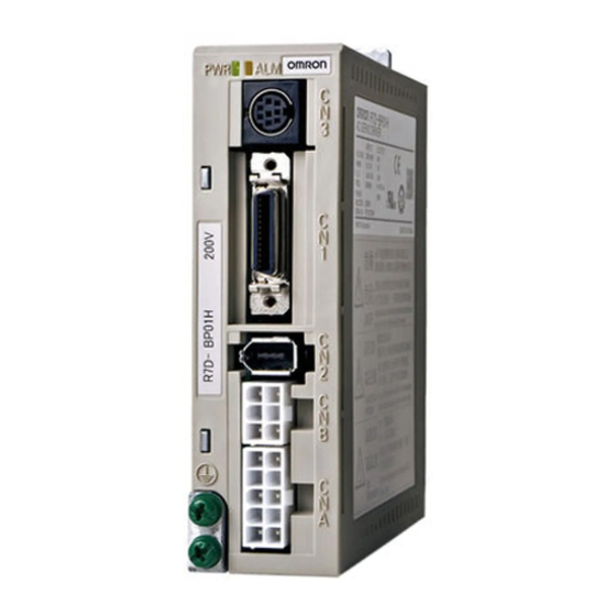
R7D@, R88D-GP08H
SmartStep 2 servo drive
Another step forward in drive simplicity
• On-line Auto-tuning and Easy set up
• Ultra-compact size. The footprint is only 48% that of
the SmartStep series
• Two torque limits
• Electronic gear, four internal speed settings and
wide range of pulse settings
• Adaptive filters for suppresion of vibration and
resonance
• Configuration and commissioning using CX Drive-
software
Ratings
• 230 VAC single-phase 50 W to 750 W (0.16 to
2.4 Nm)
System configuration
(Refer to G-Series servomotors chapter)
G-Series
servo motor
SmartStep 2 servo drive
SmartStep 2
servo drive
Encoder cable
Power cable
Brake cable
Position control
unit
Connector terminal block
General purpose controller
(with pulse output)
Personal computer
software: CX-One
Position control
unit
89
Advertisement

Subscribe to Our Youtube Channel
Related Manuals for Omron SMARTSTEP 2 SERVO DRIVE


Summary of Contents for Omron SMARTSTEP 2 SERVO DRIVE
- Page 1 • Adaptive filters for suppresion of vibration and resonance • Configuration and commissioning using CX Drive- software Ratings • 230 VAC single-phase 50 W to 750 W (0.16 to 2.4 Nm) System configuration (Refer to G-Series servomotors chapter) Personal computer...
- Page 2 Servo motor / servo drive combination Servo motor SmartStep2 servo drive Family Voltage Speed Rated torque Capacity Model Cylindric 50 -750 W 230 V 3000 min 0.16 Nm 50 W R88M-G05030H-@S2 R7D-BP01H 0.32 Nm 100 W R88M-G10030H-@S2 R7D-BP01H 0.64 Nm...
-
Page 3: Servo Drive Specifications
Between power supply/power line terminals and frame ground: 0.5 M min. (at 500 VDC) Dielectric strength Between power supply/power terminals and frame ground: 1,500 VAC for 1 min at 50/60 Hz Between each control signal and frame ground: 500 VAC for 1 min Protective structure Built into panel (IP10). - Page 4 SmartStep2 Servo Drive (750 W model) Display area AC SERVO DRIVER UNIT No. Settings area Analog monitor outputs DATA RS-485 Communications connector Main-circuit power terminals (CN3A) RS-232 Communications connector/ Parameter unit connector Control-circuit power terminals (CN3B) Control I/O connector (CN1)
- Page 5 Dimensions Servo drives R7D-BP01H (230 V, 100 W) R7D-BP02HH/04H (230 V, 200-400 W) Mounting Hole Mounting Hole Dimensions Dimensions Two, M4 Two, M4 R88D-GP08H (230 V, 750 W) Two, M4 AC SERVO DRIVER UNIT No. DATA ±0.5 Filters R7A-FIB104-RE R88A-FIK107-RE 40±1...
-
Page 6: Installation
Shell, 26 Frame ground *1. An External Regeneration Resistor can be connected. Connect this resistor if the regenerative energy exceeds regeneration absorption capacity in the Servo Drive. Note:1. The dynamic brake operates when the main circuit power supply or the control circuit power supply is turned OFF. - Page 7 Shell *1 B3-B2 are short-circuited. If the internal regenerative resistor is insufficient, remove the wire between B2 and B3 and connect an external regen- erative resistor between B1 and B2. *2 Use only when an absolute encoder. If a backup battery is connected, an encoder cable with a battery is not required.
-
Page 8: Ordering Information
General purpose signals Filter (with pulse output) ABCDE Note: The symbols ... show the recommended sequence to select the components in a SmartStep 2 servo system Servo motor ABCD Note: refer to G-Series motor chapter for detailed motor specifications and selection. - Page 9 Terminal block cable For general purpose controllers XW2Z-100J-B28 XW2Z-200J-B28 Terminal block ( with M3 screw and for pin terminals) XW2B-34G4 Terminal block ( with M3.5 screw and for fork/round terminals) XW2B-34G5 Terminal block ( with M3 screw and fork/round pin terminals)
- Page 10 General purpose signals (with pulse output) ABCDE Note: The symbols ... show the recommended sequence to select the components in a SmartStep 2 servo system. Servo motor ACDE Note: refer to G-Series motor chapter for detailed motor specifications and selection.
- Page 11 R88A-CPG001S R88A-CPG002S Terminal block cable For general purpose controllers XW2Z-100J-B24 XW2Z-200J-B24 Terminal block (M3 screw and for pin terminals) XW2B-50G4 Terminal block (M3.5 screw and for fork/round terminals) XW2B-50G5 Terminal block (M3 screw and for fork/found terminals) XW2D-50G6 Computer cable (for CN3)
- Page 12 ALL DIMENSIONS SHOWN ARE IN MILLIMETERS. To convert millimeters into inches, multiply by 0.03937. To convert grams into ounces, multiply by 0.03527. In the interest of product improvement, specifications are subject to change without notice. Cat. No. I106E-EN-02A AC servo systems...
Need help?
Do you have a question about the SMARTSTEP 2 SERVO DRIVE and is the answer not in the manual?
Questions and answers