
Related Manuals for Fab Fours N545X


Summary of Contents for Fab Fours N545X
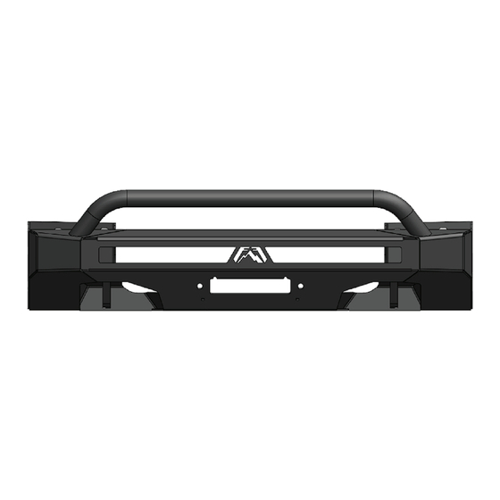
- Page 1 Installation manual TOYOTA TUNDRA Hidden winch mount part number: n545x Application: 2022 TOYOTA tundra...
- Page 2 Use own good judgment and take your time. WARNINGS • Failure to observe the following warnings • Fab Fours, Inc. only approves installing this and instructions provided in this manual product according to these written instructions could lead to severe injury and/or death.
-
Page 3: Table Of Contents
SAFETY / DISCLAIMER TABLE OF CONTENTS A MESSAGE FROM THE OWNER GETTING STARTED PROVIDED MATERIALS HARDWARE KIT INSTALLATION CONTACT... -
Page 4: A Message From The Owner
A message from the owner Fab Fours’ was born out of a passion for customizing vehicles and a love of the outdoors. Our engineering team uses the latest 3D design software to turn new product ideas into reality. In our factory, designs come to life with the combination of cutting edge technology for metal cutting and forming and an American workforce that puts its’... -
Page 5: Getting Started
Getting started Before you begin the installation process of your new Fab Fours product, we suggest laying out all materials and parts on a pad or protective surface. Failure to fully account for all components before beginning installation may leave vehicle... -
Page 6: Provided Materials
Failure to keep track of parts could lead to an inability to properly reinstall components. 20296 - 1/2” BOLT STRIP QTY:2 21871 - SIDE VALANCE L-BRACKETS QTY:2 N545X-IM 221859 – 7/16 WELD 50322-HW – INSTRUCTION NUT BRACKET QTY:2 HARDWARE KIT... - Page 7 Hardware kit | N545X-IM Fab Fours Component Identification Description 50322-HW Black Plastic Winch Tray Plugs 50322-HW 1/2", SAE, Yellow-zinc, Grade 8, Lock washer 50322-HW 1/2”-13 Yellow Zinc Hex Nut, Grade 8 50322-HW 1/2" Yellow Zinc Flat Washer, Grade 8 50322-HW 1/2”...
-
Page 8: Installation
installation 1. Use a 10mm socket to remove the 4x bolts holding the top of the grille to the radiator frame (Figure 1.). Use a body pry tool to remove the 2x push pins on the sides of the top grill and unplug the wiring harness (Figure 2.). - Page 9 3. Use a 10mm socket to remove the 5x bolts on the front of the wheel wells to access the valance body clips. Figure 4. Figure 4 4. Carefully use a body pry tool to disengage the panel clips holding the fender flare onto the truck. Pull the flare away from the body to access the valance clips.
- Page 10 5. Remove the grill and bumper assembly from the truck by carefully disengaging the lower grille panel clips. Set the grill assembly aside for disassembly. 6. Use a 17mm socket to remove the 8x bolts (2x on top 2x on bottom) holding the crash bar to the frame rails.
- Page 11 7. Use a Phillips head screwdriver to remove the bolts on the air dam housing. Figure 8. Figure 8 8. Use a 10mm socket and a Phillips head to remove the 2x hex head bolts and 1x screw respectively. Remove the motor assembly from the housing.
- Page 12 9. Remove the white plastic gear from the motor assembly by pulling it off. Figure 10. Figure 10 10. Use a Phillips head to remove the 3x bolts holding the gear and shaft in place. Remove the gear and shaft from the assembly.
- Page 13 11. Remove the E-clip from the linkage pin. Set the gear shaft linkage aside for later assembly. Figure 13. Figure 13 12. Use a cutting too to remove the access gusset material on the air dam motor housing. Figure 14-18. Figure 14 Figure 15 Figures continued on next page...
- Page 14 Figure 16 Figure 17 Figure 18 13. Reverse steps 6-10 to put the motor assembly back together. Include the shaft linkage removed in step 10.
- Page 15 14. Use a 1/4” drill bit to drill 2x holes in the motor assembly to attach it to the provided mounting bracket (22610). Use the provided ¼” yellow zinc bolts with washers and nuts. Figure 19. Figure 19 15. Use a 12mm and 10mm socket to relocate the passenger side horn to the 10mm bolt. This will allow room for the air dam relocation.
- Page 16 16. Use the provided ¼” yellow zinc bolts with washers and nuts to attach the air dam relocation bracket to the grill mounts. Plug in the air dam motor to its harness. Figure 22. Figure 22 17. Use a body pry tool to unclip and remove the lower center section of the bumper. Figure 23. Figure 23...
- Page 17 18. Use a body pry tool to remove the wire harness clips from the lower center before cutting. Figure 24-25. Figure 25 Figure 24 19. Draw a line along the border of the center section as shown in Figure 26-27. Figure 26 Figure 27...
- Page 18 20. Use a cutting tool to cut out the center section. 21. Place the provided 7/16” weld nut bracket into the driver and passenger side frames over the lower frame hole. Figure 28. Figure 28 22. Place the mounting supports (22636 and 22637) on the driver and passenger side frames. Use the provided 7/16”...
- Page 19 23. If installing a 30” light bar, do so now using the provided ¼” bolts with short L-brackets (22643). Position the light bar as desired and fully tighten mounting hardware. Figure 31. Figure 31 24. Install your winch at this time using the manufacturing hardware. 25.
- Page 20 26. Place the front grill and facia back on the truck by reversing steps 1-4. Figure 33. Figure 33 27. Position the bumper and fully tighten all mounting hardware. Figure 34. Figure 34...
- Page 21 28. Use the provided large L-brackets (21870) with the 1/4” yellow zinc bolts washers and nuts to fasten the lower facia to the bumper. Use the 1/4” stainless steel fender washer on top of the plastic mount. Note: Do not over tighten or the plastic will break. Figure 35. Figure 35 29.
- Page 22 Contact information Fab Fours Inc. 2213 Industrial Park Road Lancaster, SC 29720 Phone: (866) 385-1905 Fax: 970-385-1914 Email: support@fabfours.com fabfours.com...
- Page 23 “If you’re looking for more of the same, Then you’ve come to the wrong place.” - Greg Higgs...
Need help?
Do you have a question about the N545X and is the answer not in the manual?
Questions and answers