Table of Contents
Advertisement
Quick Links
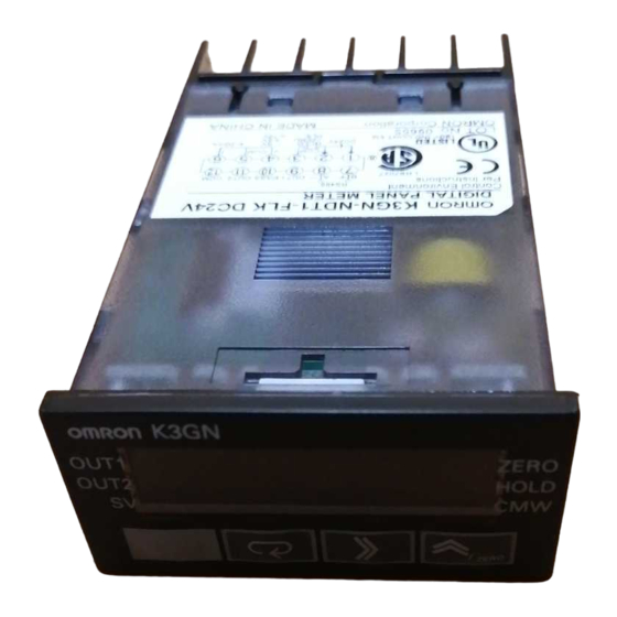
1/32 DIN Digital Panel Meter
K3GN
Compact and Intelligent Digital Panel Meter
• A single Panel Meter covering a wide range of applications.
3 main applicable functions:
• Process meter (DC voltage/current input).
• RPM processor/tachometer (frequency input).
• Digital data display for PC/PLC (RS-485 communications).
• Easy configuration
• Multi-range analog input: applicable for all standard analog
signals.
6 input ranges available: 4 to 20 mA/0 to 20 mA, 1 to 5 VDC/
0 to 5 VDC, 5 VDC, 10 VDC.
• 5 KHz max. input-pulse frequency range.
• Scaling in a wide range of engineering units.
• Programmable output operation action, decimal point
position setting, teaching function for input range, leading
zero suppression, average processing.
• Advanced and compact design
• Very compact 1/32 DIN housing: 48 (W) x 24 (H) x 83 (D).
• 5-digit display with programmable display color in red or
green.
• Good visibility: High contrast backlit LCD display.
• High protection against water and dust: NEMA4X/IP66 front
panel.
• Selectable outputs: 2 relay outputs, 3 transistor outputs,
RS-485, and combinations of these.
• High accuracy: 0.1% full scale.
• Easy to configure through the front panel or via RS-485.
• EN/IEC conformity with CE marking and UL/CSA approval.
Model Number Structure
■ Model Number Legend
K3GN -
-
24 VDC
1
2
3
1. Input Type
ND:
DC voltage/current, NPN
PD:
DC voltage/current, PNP
2. Output Type
C:
2 relay contact outputs (SPST-NO)
T1:
3 transistor outputs (NPN open collector)
T2:
3 transistor outputs (PNP open collector)
3. Communications Output Type
None: Communications not supported
FLK: RS-485
1/32 DIN Digital Panel Meter
®
K3GN
K-7
Advertisement
Table of Contents

Related Manuals for Omron K3GN - V1.03


Summary of Contents for Omron K3GN - V1.03
- Page 1 • Multi-range analog input: applicable for all standard analog signals. 6 input ranges available: 4 to 20 mA/0 to 20 mA, 1 to 5 VDC/ 0 to 5 VDC, 5 VDC, 10 VDC. • 5 KHz max. input-pulse frequency range.
-
Page 2: Ordering Information
Approx. 100 g Note: A control power supply capacity greater than the rated capacity is required when the Digital Panel Meter is turned ON. Do not forget to take this into consideration when using several Digital Panel Meters. When power is supplied, all indicators will light and outputs will be OFF. - Page 3 “ ” is displayed automatically with a negative input signal. Zero display Leading zeros are not displayed. Scaling function Programmable with front-panel key inputs (range of display: 19999 to 99999). The decimal point position can be set as desired. External controls HOLD: (Measurement value held)
- Page 4 Mechanical life 50,000,000 times min. (at a switching frequency of 36,000 times/hr) Electrical life 100,000 times min. (at the rated load with a switching frequency of 1,800 times/hr) (at an ambient temperature of 23 C) Transistor Output Rated load voltage 24 VDC Max.
- Page 5 Operation power supply 24 VDC* Voltage Current Analog input Event or pulse/contact input Note: *Operation power supply 24VDC: Recommended DC power supply: eg. OMRON s8VS Terminal No. Name Description Operation power Connect the operation power supply. Event input or pulse/contact input...
-
Page 6: Block Diagram
Constant voltage circuit 1 Constant voltage circuit 2 Power supply circuit Note: 1. Transistor output models only. 2. Relay output models only. 3. Models with communications functions only. Operating power supply Input Circuits Analog Input (DC Voltage/Current) -
Page 7: Output Circuits
Output Circuits Contact Output OUT1 OUT2 OUT3 Transistor Output NPN Output PNP Output OUT1 PASS OUT2 PASS OUT2 OUT1 K3GN K-13 1/32 DIN Digital Panel Meter... -
Page 8: Operation
Any input value D = f DISPLAY2: Displayed value corresponding to INPUT2 so if f = 1, then D = 12. Therefore, input 1 for inp and 12 for dsp. INPUT1: Any input value DISPLAY1: Displayed value corresponding to INPUT1... -
Page 9: Changing The Display Color
An upper limit (H set value) and lower limit (L set value) can be set independently. The output is turned ON when the measured value is greater than upper-limit set value or less than the lower-limit set value. Only transistor outputs have a PASS output which is output when both OUT1 and OUT2 are OFF. - Page 10 5. Mode Key Used to allow the Main display to indicate parameters sequentially. 6. Shift Key Used to enable that set value to be changed. When changing a set value, this key is used to move along the digits. 7. Up/Zero Key Used to change a set value.
-
Page 11: Application Examples
Application Examples Detection of Dust Exhaust Monitoring of Tank Pressure The change in the density of the dust is detected via the E3SA and The output of the pressure sensor is processed and the pressure is discriminated by the K3GN. - Page 12 Monitoring Number of Motor Line Speeds Revolutions The difference between the two line speeds is calculated by the PLC and the result is written via RS-485 to the K3GN where it is dis- played. Power supply* Signal input 24-VDC power supply*...
- Page 13 A K3GN model with a relay contact or transistor output may not out- uct failure or malfunction. put any alarm signal normally if the model has an error. It is recom- mended that an independent alarm device be connected to the !Caution model.
-
Page 14: Operating Procedures
Operating Procedures ■ Initial Settings Power ON Press the Level Key @ for 3 s min. to move to the initial setting level. Select the input type and specify the analog input range or pulse frequency input range. Set the scaling values and specify output operating action as required. - Page 15 ■ Levels “Level” refers to a grouping of parameters. The following table lists the operations that are possible in each of the levels, and how to move between levels. There are some parameters that are not displayed for certain models.
- Page 16 ■ Parameters Note: 1. Some parameters are not displayed for certain models. 2. The K3GN will stop measurement if the level is changed to the initial setting level, the advanced function setting level, the communications setting level, or the calibration level.
- Page 17 Press Level Key for less than 1 s. Communications setting level Commu- nications unit no. Baud rate Word length Stop bits None Parity bits Even Press Level Key for more than 3 s. Press Level Key for more than 1 s.
- Page 18 • Initial setting is 0. Allowed (message for mov- Allowed • When the set value is 0 (the initial setting), protection is not set. ing to advanced function setting level not displayed) Setting Change Lockout Prohibited Prohibited Prohibits setting changes.
- Page 19 ■ Troubleshooting When an error occurs, error details will be displayed on the main display. Confirm the error from the main display and take the appropriate coun- termeasures. Main display Level Error contents Countermeasure display e111 (E111) Not lit RAM memory error Turn the power supply OFF and ON again.
-
Page 20: Additional Information
Additional Information ■ Application as a Process Meter The initial settings required when using the K3GN a process meter are explained below using the following example. Setting Example Initial Setting Procedure Inputs in the range 1 to 5 V are scaled to the range 0 to 100.0 kg and 1. - Page 21 Set parameter in-t to pulse. 3. Set the pulse frequency to 30 Hz. The input pulse frequency for the application is approximately 2 Hz and so can be assumed not to exceed 30 Hz. Set parameter p-fre to 30. 4. Set the scaling values.
- Page 22 ALL DIMENSIONS SHOWN ARE IN MILLIMETERS. To convert millimeters into inches, multiply by 0.03937. To convert grams into ounces, multiply by 0.03527. In the interest of product improvement, specifications are subject to change without notice. Cat. No. N101-E1-03 K3GN K-28...
Need help?
Do you have a question about the K3GN - V1.03 and is the answer not in the manual?
Questions and answers