Table of Contents
Advertisement
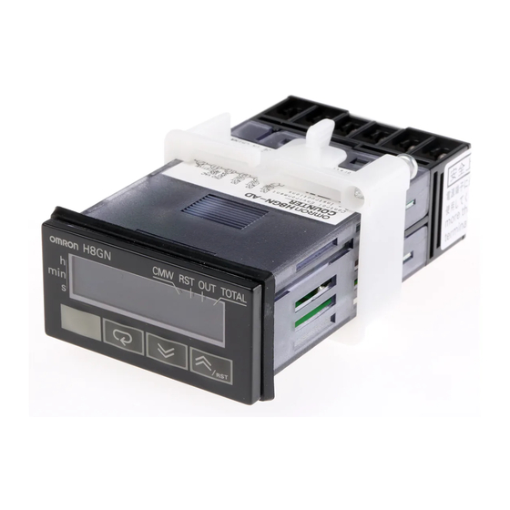
Preset Counter/Timer
H8GN
World's Smallest Compact Preset Counter/
Timer
1/32-mm DIN with Communications
• Only 48 x 24 x 83 mm (W x H x D)
• Switch between 4-digit preset counter and 4-digit timer opera-
tion.
• While using the preset counter, it is possible to switch the dis-
play to monitor the totalizing count value (8 digits).
• Built-in prescaling for counter operation.
• ON/OFF-duty adjustable flicker mode that can be used to per-
form cyclic control is available for timer operation.
• Four preset values that can be changed by the front panel key
(SV-bank).
• Finger protection terminal block to meet VDE0106/P100.
• Panel surface compatible with NEMA4X/IP66.
• Conforms to UL, CSA, and IEC safety standards as well as CE
Marking.
• Six-language instruction manual provided.
Model Number Structure
■ Model Number Legend
H8GN-AD-@
1
2
1. Supply Voltage
D:
24 VDC
Ordering Information
■ List of Models
Supply voltage
24 VDC
Output
Contact output (SPDT)
2. Communications Output Type
None: Communications not supported
FLK: RS-485
Communications
No communications
H8GN-AD
Preset Counter/Timer
RS-485
H8GN-AD-FLK
H8GN
C-59
Advertisement
Table of Contents

Subscribe to Our Youtube Channel
Related Manuals for Omron H8GN - V1.02


Summary of Contents for Omron H8GN - V1.02
-
Page 1: Model Number Structure
World’s Smallest Compact Preset Counter/ Timer 1/32-mm DIN with Communications • Only 48 x 24 x 83 mm (W x H x D) • Switch between 4-digit preset counter and 4-digit timer opera- tion. • While using the preset counter, it is possible to switch the dis- play to monitor the totalizing count value (8 digits). -
Page 2: Specifications
Time ranges 0.000 to 9.999 s, 0.00 to 99.99 s, 0.0 to 999.9 s, 0 to 9999 s, 0 min 00 s to 99 min 59 s, 0.0 to 999.9 min, 0 h 00 min to 99 h 59 min, 0.0 h to 999.9 h, 0 h to 9999 h... - Page 3 500 VAC, 50/60 Hz for 1 min between communications terminals and current-carrying termi- nals (except output terminals) 1,000 VAC, 50/60 Hz for 1 min between contacts not located next to each other Noise immunity Square-wave noise by noise simulator;...
-
Page 4: Resistive Load
SV-banks; switching between communications write-enabled/write-prohibited; reading/writing other initial and advanced function setting parameters Note: The baud rate, data bit length, stop bit length, and vertical parity can be individually set using the communications setting level. ■ Life-test Curve (Reference Values) Resistive Load Reference: A maximum current of 0.15 A can be switched at... - Page 5 CP1/CP2 • Receive count signals. • Receive increment, decrement, individual, and quadrature inputs. • In increment mode and decrement mode, CP1 is used for the count input and CP2 is used for count prohibit input. Reset • Resets the present value. (Totalizing count value is not reset.) (In increment mode or increment/decrement mode, the present value returns to 0;...
- Page 6 4 digits of the 8-digit totalizing count Lit when communications writing is enabled. will be displayed. (Zeros suppressed) Lit during reset using reset input or Reset Key. Lit when control output is ON. TOTAL Lit when totalizing count value is displayed.
- Page 7 Dimensions Note: All units are in millimeters unless otherwise indicated. Panel cutout H8GN M3 terminal screw Separate Gang mounting mounting No. of units +1.0 2.5) 40 min. The product cannot be made waterproof when gang-mounted. Insert the H8GN in the square cutout,...
- Page 8 ON, the time display will actually start from • Use the product within the ratings specified for temperature and 258 ms. If the set value is 258 ms or less, the time until output turns humidity.
- Page 9 When the output mode is set to A, B (one-shot output), D, or F, output will turn ON when the start signal is input. b) When the output mode is set to B (hold output), E, or Z, output will remain OFF even when the start signal is input.
-
Page 10: Operating Procedures
Operating Procedures ■ Initial Setup Keys are used to switch between setup menus, and the amount of time that you hold the keys down for determines which setup menu you move to. This section describes two typical examples. Note: In the following sections, “PV” is used to indicate a present value and “SV” to indicate a set value. - Page 11 Set SV Keys to set the SV to 10.0. Press the Key. Reset PV Operate Start operation Confirming Set Values Set values are effective two seconds after key operation is stopped or when the Key is pressed. H8GN C-69 Preset Counter/Timer...
- Page 12 Note: Of these levels, the initial setting level, communications setting level, and advanced function setting level can be used only when operation has stopped. Control output is stopped when these three levels are selected. When switched back to the operation level from one of these levels, operation will start.
- Page 13 (SV 0 to 3). When the set value is changed in operation been set to ON. mode, the set value (SV 0 to 3) set in the adjustment level for SV- The leftmost four digits of the 8-digit totalizing count value will be bank will also change.
-
Page 14: Initial Setting Level
(0.001 to 9.999). When the H8GN is to be used as a timer, set the time range to be Example: To have a display of @@.@@ m for a system that out- timed. - Page 15 Switches the CP1 input edge when the H8GN is used as an incre- menting or decrementing counter. In the counter increment or decrement modes, CP2 will function as the gate input and CP1 counting will be prohibited while CP2 is ON.
-
Page 16: Advanced Function Setting Level
Not protected No display, switch between SV 0 to 3. no level shift To use the SV-bank function, the set value (SV 0 to 3) must be set Not protected No display, No display, beforehand in the adjustment level. These set value are then... - Page 17 When communicating with a host computer, set a unit number to enable the host computer to identify each unit. The number can be set in a range from 0 to 99 in increments of 1. The default unit number is 1. When using multiple units, the units will not function normally if the same unit number is set for more than one unit.
- Page 18 : B* When Output timer mode for selected timer When the Note : The parameters shown in reverse video are above C*, : 0.01 to 99.99 s Output Counter the default settings. K*, A*, or time Timer : 0.00 to 99.99 s B* mode Output will be held if output time is 0.
- Page 19 Key for more than set time (The default setting is 3 s.) Adjustment level Protect level Key for 1 s. min. : Level 0 Commu- Operation/ Models with : Enabled : Level 1 nications adjustment communications : Disabled : Level 2...
- Page 20 Count Count Note: 1. (A) indicates the minimum signal width and (B) requires at least 1/2 the minimum signal width. If these conditions are not met, a counting error (+1 or 1) may occur. 2. The following table explains the L and H symbols in the above graphics.
- Page 21 : Less than the output time. 2. If there is a power failure during output ON, output will turn ON again when the power supply has recovered. For one-shot output, an output will be made again for the duration of the output time setting once the power supply has resumed.
-
Page 22: Timer Function
The set value shows the ON duty (%) and can be set to a value between 0 and 100 (%). When the cycle time is 0, the output will always be OFF. When the cycle time is not 0 and when ON duty has been set to 0 (%), the output will always be OFF. When ON duty has been set to 100 (%), the output will always be ON. -
Page 23: Troubleshooting
■ Troubleshooting When an error occurs, the error code is displayed on the main display. Take countermeasures according to the code. No. 1 display No. 2 display Error contents Countermeasure No display Memory error (RAM) Turn the power OFF and ON again. If normal operation is still not restored, e111 it may be necessary to repair or replace the H8GN. -
Page 24: Additional Information
Additional Information ■ Parameters List Fill in your set values in the Set value column of the following tables and utilize the tables for quick reference. Protect Level Parameter name Parameter Setting range Default Unit Set value value Operation/Adjustment Protection... -
Page 25: Adjustment Level
Communications writing cmwt on/off control SV 0 sp-0 Same as for PV in the above PV/SV column. SV 1 sp-1 Same as for PV in the above PV/SV column. SV 2 sp-2 Same as for PV in the above PV/SV column. - Page 26 Second prlt ALL DIMENSIONS SHOWN ARE IN MILLIMETERS. To convert millimeters into inches, multiply by 0.03937. To convert grams into ounces, multiply by 0.03527. In the interest of product improvement, specifications are subject to change without notice. Cat. No. M065-E1-02...
Need help?
Do you have a question about the H8GN - V1.02 and is the answer not in the manual?
Questions and answers