
Related Manuals for Omron H8GN


Summary of Contents for Omron H8GN
- Page 1 2000-09-26 PRODUKTINFORMATION Vi reserverar oss mot fel samt förbehåller oss rätten till ändringar utan föregående meddelande ELFA artikelnr 37-768-04 Räknare/Tidrelä H8GN...
-
Page 2: Ordering Information
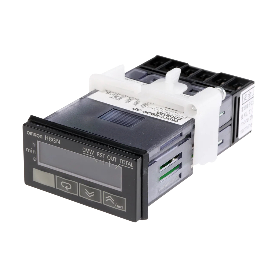
Preset Counter/Timer H8GN World’s Smallest Compact Preset Counter/Timer 1/32-mm DIN with Communications Only 48 x 24 x 83 mm (W x H x D) Switch between 4-digit preset counter and 4-digit timer operation. While using the preset counter, it is possible to switch the display to monitor the totalizing count value (8 digits). -
Page 3: Specifications
H8GN H8GN Specifications Ratings Rated supply voltage 24 VDC Operating voltage range 85% to 110% of rated supply voltage Power consumption 1.5 W max. (for max. DC load) (Inrush current: 15 A max.) Mounting method Flush mounting External connections Screw terminals (M3 screws) Terminal screw tightening torque 0.5 N m max. - Page 4 H8GN H8GN Characteristics Timer function Accuracy of Signal start: 0.03% 30 ms max. operating time and Power-ON start: 0.03% 50 ms max. setting error (including temperature and voltage effects) Insulation resistance 100 MΩ min. (at 500 VDC) Dialectic strength 1,500 VAC, 50/60 Hz for 1 min between output terminals and non-current-carrying...
-
Page 5: Communications Specifications
Retry function Not supported. Communications buffer 40 bytes Reading and writing from H8GN Reading present value and totalizing count value; reading/writing preset and set values; switching between SV-banks; switching between communications write-enabled/write-prohibited; reading/writing other initial and advanced function setting parameters... - Page 6 4 digits of 123.4 s the count value (8 digits) when the Flashes while timer is on 0.0 min, H8GN is used as a 0 h 00 min, 0.0 h, or 0 h. totalizing counter. (Zeros suppressed) Down Key...
-
Page 7: Operation
H8GN H8GN Operation Block Diagram (Basic Communications Output circuit insulation) circuit (Functional (Basic insulation) insulation) Display circuit Internal Input circuit control circuit Key switch circuit Power supply circuit I/O Functions CP1/CP2 Inputs Counter inputs Receive count signals. Receive increment, decrement, individual, and quadrature inputs. -
Page 8: Initial Setup
This section describes two typical examples. Note: In the following sections, “PV” is used to indicate a present value and “SV” to indicate a set value. 1. Using the H8GN as a Counter Typical Application Examples Setup Procedure 1. - Page 9 H8GN H8GN 2. Using the H8GN as a Timer Typical Application Examples Setup Procedure Power ON Power ON 1. Changing Set Values Operation Level Set value and selections in each display can be changed by pressing Keys. Present value (PV)/ set value (SV) 2.
-
Page 10: Outline Of Operation Procedure
H8GN H8GN Setting Specifications after Turning ON Power Outline of Operation Procedure Key Operation In the following descriptions, all the parameters are introduced in the display sequence. Some parameters may not be displayed depending on the protection settings and operating conditions. -
Page 11: Adjustment Level
H8GN H8GN Parameters Operation Level Adjustment Level (1) PV/SV (1) Communications writing control (2) PV (2) SV 0 (3) Totalizing count value (2) SV 1 (4) SV-bank (2) SV 2 1. PV/SV This display appears when the power is turned ON. No. 1 display (2) SV 3 shows the present value and No. -
Page 12: Initial Setting Level
Key to When the H8GN is to be used as a timer, set the time range to be move it to the right. timed. - Page 13 Switches the CP1 input edge when the H8GN is used as an in- crementing or decrementing counter. In the counter increment or decrement modes, CP2 will function as the gate input and CP1 counting will be prohibited while CP2 is ON.
-
Page 14: Advanced Function Setting Level
H8GN H8GN Advanced Function Setting Level Protect Level (1) Operation/Adjustment Protection Restricts menu display and writing in the (1) Parameter initialization operation and adjustment levels. (2) Initial Setting/Communications Protection (2) SV-bank used Restricts menu display and moving to the initial setting level/communications setting level/advanced function setting level. - Page 15 H8GN H8GN The default setting is OFF.
-
Page 16: Communications Setting Level
H8GN H8GN Communications Setting Level (sbit) 4. Stop Bits The communications specifications are set in the communications The stop bits can be set to either 1 or 2. setting level. Make the individual communications settings from the (prty) 5. Parity front panel. - Page 17 H8GN H8GN Parameters Power ON Power ON Keys Key 1 s. min. Key less than 1s. 3 s. min. (default value) Operation level Key 3 s. min. Adjustment Operation level Protect level level less than 1 s. See note 1.
- Page 18 H8GN H8GN Key for more than set time (The default setting is 3 s.) Adjustment level Protect level Key for 1 s. min. : Level 0 Communic Models with Operation/ : Enabled : Level 1 ations communications adjustment : Level 2...
-
Page 19: Operating Mode
H8GN H8GN Operating Mode Input/Output Modes and Count Values Up (Increment) mode Down (Decrement) mode Input CP1: Count input CP2: Count prohibit input CP1: Count input CP2: Count prohibit input edge Count Count prohibit prohibit n–1 n–2 n–3 Count Count n–4... - Page 20 H8GN H8GN Input/Output Mode Settings Counter Function Input mode Down Up/Down B.C Output Reset mode 9999 –999 Output Reset 9999 –999 Output Reset 9999 –999 t–a t–a Output Reset 9999 –999 t–a t–a t–a t–a Output Note: 1. t: output time. t – a < t : Less than the output time.
- Page 21 H8GN H8GN Timer Function A mode: Signal ON-delay (See note.) B mode: Flicker (See note.) Power Power supply supply Start Start Gate Gate Reset Reset Control Control output output DOWN DOWN D mode: Signal OFF-delay E mode: Interval Power Power...
-
Page 22: Troubleshooting
Turn the power OFF and ON again. If normal operation is still not No display Memory error restored, it may be necessary to repair or replace the H8GN. If (RAM) normal operation is restored by turning the power supply OFF and... - Page 23 Store at the specified temperature. If the H8GN has been stored at a temperature of less than –10 C, allow the H8GN to stand at Timer Control with Power Start room temperature for at least 3 hours before use.
- Page 24 4X (indoors) and IP66). In order to prevent the internal circuit from water penetration through the space between the Counter and op- erating panel, attach a rubber packing (provided with the H8GN) be- tween the Counter and operating panel and secure the rubber pack-...
-
Page 25: Parameters List
H8GN H8GN Appendix Parameters List Fill in your set values in the Set value column of the following tables and utilize the tables for quick reference. Protect Level Parameter name Parameter Setting range Default Unit Set value value oapt 0 to 3... - Page 26 H8GN H8GN Adjustment Level Parameter name Parameter Setting range Default Unit Set value value cmwt on/off Communications writing control sp-0 SV 0 Same as for PV in the above PV/SV column. sp-1 SV 1 Same as for PV in the above PV/SV column.
- Page 27 H8GN H8GN Advanced Function Setting Level Parameter name Parameter Setting range Default Unit Set value value init on/off Parameter initialization mspu on/off SV-bank used tcnu on/off Totalizing counter used off/1 to 99 Display auto-return time Second prlt 3 to 30...
Need help?
Do you have a question about the H8GN and is the answer not in the manual?
Questions and answers