Advertisement
Table of Contents
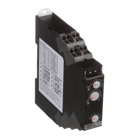
Datenblatt
Zeitrelais H3DT
H3DT
Bezeichnung
Schutzgrad
Betriebstemperatur
Zertifizierung
Versorgungsspannung
Ausgänge
Eingang
Anzahl Kontakte
Zeitbereich
Kontaktkonfiguration
Erstellt am 09.10.2020 um 23:38 Uhr | Alle Angaben ohne Gewähr, Irrtümer und Änderungen vorbehalten!
|
ATEG Automation GmbH
Intzestraße 50
H3DT
IP30
-20°C ... 60°C
cULus: UL 508/CSA, LR/ DNV GL
24 - 240 VAC/DC
max.5 A bei 250 VAC, Relais,
Spannungseingang
1 Wechsler, 2 Wechsler
0,1s - 1200h
programmierbare Kontakte
|
|
42859 Remscheid
Germany
|
Tel.: +49 (0)2191 / 591457-0
Seite 1 von 37
|
| www.ateg.de
info@ateg.de
Advertisement
Table of Contents

Subscribe to Our Youtube Channel
Related Manuals for Omron Ateg H3DT Series


Summary of Contents for Omron Ateg H3DT Series
- Page 1 Datenblatt Zeitrelais H3DT H3DT Bezeichnung H3DT Schutzgrad IP30 Betriebstemperatur -20°C ... 60°C Zertifizierung cULus: UL 508/CSA, LR/ DNV GL Versorgungsspannung 24 - 240 VAC/DC Ausgänge max.5 A bei 250 VAC, Relais, Eingang Spannungseingang Anzahl Kontakte 1 Wechsler, 2 Wechsler Zeitbereich 0,1s - 1200h Kontaktkonfiguration programmierbare Kontakte...
- Page 2 *1. According to OMRON investigation in October 2015. For the most recent information on models that have been *2. Based on OMRON comparison (excluding the H3DT-H). certified for safety standards, refer to your OMRON website. *3. Certification is pending for DNV GL. Model Number Structure...
- Page 3 • Sequence checks are easily performed by setting an instantaneous output to 0. • Start signal control for some operating modes. For the most recent information on models that have been certified for safety standards, refer to your OMRON website. Ordering Information List of Models H3DT-N/H3DT-L...
- Page 4 Datenblatt Zeitrelais H3DT H3DT H3DT-N/H3DT-L Specifications Time Ranges Time range setting 0.1 s 10 s 1 min 10 min 10 h 100 h Set time range 0.1 to 1.2 s 1 to 12 s 10 to 120 s 1 to 12 min 10 to 120 min 1 to 12 h 10 to 120 h...
-
Page 5: Applicable Standards
Datenblatt Zeitrelais H3DT H3DT H3DT-N/H3DT-L Characteristics Installation Pitch and Output Accuracy of operating 1% of FS max. (1% 10 ms max. at 1.2-s range) time Switching Capacity (Reference 10% of FS 0.05 s max. Setting error Values) Minimum input signal The relation between the installation pitch and 50 ms (start input) width... -
Page 6: Terminal Arrangement
Datenblatt Zeitrelais H3DT H3DT H3DT-N/H3DT-L Connections Block Diagrams H3DT-N/L Time setting Time specification Operating mode AC (DC) input detection circuit switches switch Clock Power supply circuit Output circuit One-chip microcomputer Start input Input circuit Indicator circuit Power Output indicator indicator Terminal Arrangement H3DT-N1/L1 H3DT-N2/L2... -
Page 7: Input Connections
Datenblatt Zeitrelais H3DT H3DT H3DT-N/H3DT-L Input Connections The start input is a voltage input. PNP Transistor Input NPN Transistor Input Relay Input Voltage Input Signal Levels Sensor 1. Transistor ON 24 VDC 24 VDC • Residual voltage: 1 V max. (sensor Timer Sensor... - Page 8 Datenblatt Zeitrelais H3DT H3DT H3DT-N/H3DT-L Dimensions (Unit: mm) Timers H3DT-N H3DT-L 17.5 17.5 H3DT-N2 H3DT-N1 H3DT-L2 H3DT-L1 H3DT-N2 H3DT-N1 H3DT-L2 H3DT-L1 Track Mounting Products (Sold Separately) Refer to page 29 for details. Options (Order Separately) Front Cover Refer to page 29 for details. Operating Procedures Basic Operation Setting Switches...
-
Page 9: Timing Charts
Datenblatt Zeitrelais H3DT H3DT H3DT-N/H3DT-L Timing Charts • There is no instantaneous output with the H3DT-N1/L1. A2: ON Delay (Power ON Delay) Basic Operation − − Power (A1 and A2) Time-limit contacts: NC Power 15 and 16 (25 and 26) Timing Time-limit contacts: NO (output indicator) - Page 10 Datenblatt Zeitrelais H3DT H3DT H3DT-N/H3DT-L E2: Interval (Power ON Start) Basic Operation − − Power (A1 and A2) Time-limit contacts: NC Power 15 and 16 (25 and 26) Timing Time-limit contacts: NO Output (output indicator) 15 and 18 (25 and 28) Instantaneous contacts: NC (21 and 22) Instantaneous contacts: NO...
- Page 11 Datenblatt Zeitrelais H3DT H3DT H3DT-N/H3DT-L A: ON Delay (Signal ON Delay) Basic Operation − Power (A1 and A2) Start input (B1 and A1) Power Time-limit contacts: NC 15 and 16 (25 and 26) Start input Time-limit contacts: NO (output indicator) Timing 15 and 18 (25 and 28) Output...
- Page 12 Datenblatt Zeitrelais H3DT H3DT H3DT-N/H3DT-L E: Interval (Signal Start) Basic Operation − − − Power (A1 and A2) Start input (B1 and A1) Power Time-limit contacts: NC 15 and 16 (25 and 26) Start input Time-limit contacts: NO Timing (output indicator) Output 15 and 18 (25 and 28) Instantaneous contacts: NC...
- Page 13 • Single Mode Timers with power ON delay operation. * CSA conformance evaluation by UL. For the most recent information on models that have been certified for safety standards, refer to your OMRON website. Ordering Information List of Models Supply voltage...
- Page 14 Datenblatt Zeitrelais H3DT H3DT H3DT-A Characteristics Installation Pitch and Output Accuracy of operating 1% of FS max. (1% 10 ms max. at 1.2-s range) time Switching Capacity (Reference 10% of FS 0.05 s max. Setting error Values) 0.5% of FS max. (0.5% 10 ms max. at 1.2-s range) Influence of voltage The relation between the installation pitch and the load current is shown in the following...
- Page 15 Datenblatt Zeitrelais H3DT H3DT H3DT-A Connections Block Diagrams H3DT-A Time setting Time specification AC (DC) input detection circuit switches Clock Power supply circuit Output circuit One-chip microcomputer Indicator circuit Power Output indicator indicator Terminal Arrangement H3DT-A1 H3DT-A2 * The power supply terminals do not have polarity. (DIN notation) (DIN notation) Erstellt am 09.10.2020 um 23:38 Uhr | Alle Angaben ohne Gewähr, Irrtümer und Änderungen vorbehalten!
- Page 16 Datenblatt Zeitrelais H3DT H3DT H3DT-A Nomenclature H3DT-A2 H3DT-A1 Front View Front View Time range switch * Time range switch * Operation/power indicator (green) Operation/power indicator (green) (Flashes while Timer is operating. (Flashes while Timer is operating. Lit when Timer is stopped.) Main dial Lit when Timer is stopped.) Main dial...
-
Page 17: Setting Switches
Datenblatt Zeitrelais H3DT H3DT H3DT-A Operating Procedures Basic Operation Setting Switches • Each switch has a snap mechanism that secures the switch at given positions. Set the switch to one of these positions. Do not set it midway between two positions. Malfunction could result from an improper setting. Setting the Time Range Setting the Time Range The time range switch can be used to set... - Page 18 * CSA conformance evaluation by UL. • Eight time ranges from 0.1 s to 1,200 h. For the most recent information on models that have been certified for safety standards, refer to your OMRON website. Ordering Information List of Models...
- Page 19 Datenblatt Zeitrelais H3DT H3DT H3DT-F Characteristics Installation Pitch and Output Accuracy of operating 1% of FS max. (1% 10 ms max. at 1.2-s range) time Switching Capacity (Reference 10% of FS 0.05 s max. Setting error Values) 0.5% of FS max. (0.5% 10 ms max. at 1.2-s range) Influence of voltage The relation between the installation pitch and the load current is shown in the following...
- Page 20 Datenblatt Zeitrelais H3DT H3DT H3DT-F Connections Terminal Arrangement Block Diagrams H3DT-F H3DT-F indicator indicator ON/OFF time setting ON/OFF start switch detection circuit Time AC (DC) specification Indicator input switches circuit Clock One-chip microcomputer Power supply Output circuit circuit (DIN notation) * The power supply terminals do not have polarity.
- Page 21 Datenblatt Zeitrelais H3DT H3DT H3DT-F Dimensions (Unit: mm) Timers H3DT-F 17.5 Track Mounting Products (Sold Separately) Refer to page 29 for details. Options (Order Separately) Front Cover Refer to page 29 for details. Operating Procedures Basic Operation Setting the Time Ranges Setting the ON/OFF Start Switch Setting the Times Setting the Time Ranges...
- Page 22 • Set two time ranges between 1 and 120 s with one Timer. * CSA conformance evaluation by UL. For the most recent information on models that have been certified for safety standards, refer to your OMRON website. Ordering Information List of Models...
- Page 23 Datenblatt Zeitrelais H3DT H3DT H3DT-G Characteristics Installation Pitch and Output Accuracy of operating 1% of FS max. time Switching Capacity (Reference 10% of FS 0.05 s max. Setting error Values) Total error (25% of transfer time + 5 ms) max. Transfer time The relation between the installation pitch 0.5% of FS max.
- Page 24 Datenblatt Zeitrelais H3DT H3DT H3DT-G Connections Block Diagrams H3DT-G Terminal Arrangement H3DT-G AC (DC) input Star time Star-delta setting transfer time switch switch Star output Power supply circuit Output Clock circuit Delta output One-chip microcomputer Star Delta contacts contacts Indicator circuit Star output ON Delta output ON indicator...
-
Page 25: Timing Chart
Datenblatt Zeitrelais H3DT H3DT H3DT-G Dimensions (Unit: mm) Timers H3DT-G 17.5 Track Mounting Products (Sold Separately) Refer to page 29 for details. Options (Order Separately) Front Cover Refer to page 29 for details. Operating Procedures Basic Operation Setting the Time Ranges Setting the Time Setting the Delta Time Range (t1) and Setting the Time... - Page 26 * CSA conformance evaluation by UL. for the S Series and from 1.0 to 120 seconds for the L Series. For the most recent information on models that have been certified for safety standards, refer to your OMRON website. Ordering Information List of Models...
- Page 27 Datenblatt Zeitrelais H3DT H3DT H3DT-H Characteristics Installation Pitch and Output Accuracy of operating 1% of FS max. (1% 10 ms max. at 1.2-s range) time Switching Capacity (Reference 10% of FS 0.05 s max. Setting error Values) 0.5% of FS max. (0.5% 10 ms max. at 1.2-s range) Influence of voltage The relation between the installation pitch and the load current is shown in the following...
- Page 28 Datenblatt Zeitrelais H3DT H3DT H3DT-H Connections Block Diagrams Terminal Arrangement H3DT-H H3DT-H Time specification AC (DC) input Indicator circuit switches Power supply Oscillation circuit Counting circuit Output circuit circuit Power interruption detection circuit (DIN notation) Note: The above figure shows the terminal arrangement for a 24 to 48-VAC/DC model.
- Page 29 Datenblatt Zeitrelais H3DT H3DT H3DT-H Dimensions (Unit: mm) Timers H3DT-H 17.5 Track Mounting Products (Sold Separately) Refer to page 29 for details. Options (Order Separately) Front Cover Refer to page 29 for details. Operating Procedures Basic Operation Setting the Time Setting the Time Ranges Setting the Time Ranges Setting the Time...
- Page 30 Datenblatt Zeitrelais H3DT H3DT H3DT Track Mounting Products (Sold Separately) (Unit: mm) DIN Track PFP-100N PFP-50N ±0.15 ±0.3 ±0.15 15(5) * 1,000 (500) * * Dimensions in parentheses are for the PFP-50N. DIN Track PFP-100N2 29.2 ±0.3 1,000 End Plate PFP-M M4x8 panhead...
-
Page 31: Safety Precautions
Datenblatt Zeitrelais H3DT H3DT H3DT Safety Precautions Refer to Safety Precautions for All Timers. Format of Warning Indications Precautions for Safe Use Indicates a potentially hazardous situation • Rapid changes in temperature or high humidity may cause CAUTION which, if not avoided, may result in minor or condensation in Timer circuits, possibly resulting in malfunction or moderate injury or in property damage. - Page 32 Products that are 1. Pull out the two hooks on the back of the Timer to the outside until suitable for operation in sulfide gas are not available for OMRON you hear them click in place.
- Page 33 Datenblatt Zeitrelais H3DT H3DT H3DT Wiring • If a relay or transistor is connected to two or more Timers, the input terminals of those Timers must be wired properly so that they will 1. Connecting Wires to the Push-In Plus Terminal Block not be different in phase or the terminals will be short-circuited to Part Names of the Terminal Block one another.
-
Page 34: Operating Frequency
3. Remove the flat-blade screwdriver from the release hole. <Lower side> <Upper side> Flat-blade screwdriver 0.4 mm 2.5 mm Wire Wire Model Manufacturer XW4Z-00B Omron ESD0.40X2.5 Wera SZF 0.4X2.5 Phoenix Contact 0.4X2.5X75 302 Wiha Flat-blade screwdriver AEF.2.5X75 Facom 10 to 15°... -
Page 35: Other Precautions
Datenblatt Zeitrelais H3DT H3DT H3DT Other Precautions EN/IEC Standard Compliance • If the Timer is mounted on a control panel, dismount the Timer from the control panel before carrying out a voltage withstand test • Refer to the datasheet for the H3DK for cable selection and other between the electric circuits and non-current-carrying metal parts conditions for compliance with EMC standards. -
Page 36: Terms And Conditions Agreement
Data presented in Omron Company websites, catalogs and other materials is provided as a guide for the user in determining suitability and does not constitute a warranty. It may represent the result of Omron’s test conditions, and the user must correlate it to actual application requirements. - Page 37 The Netherlands Hoffman Estates, IL 60169 U.S.A. Tel: (31)2356-81-300/Fax: (31)2356-81-388 Tel: (1) 847-843-7900/Fax: (1) 847-843-7787 © OMRON Corporation 2016 All Rights Reserved. OMRON (CHINA) CO., LTD. OMRON ASIA PACIFIC PTE. LTD. In the interest of product improvement, No. 438A Alexandra Road # 05-05/08 (Lobby 2), Room 2211, Bank of China Tower, specifications are subject to change without notice.
Need help?
Do you have a question about the Ateg H3DT Series and is the answer not in the manual?
Questions and answers