Table of Contents
Advertisement
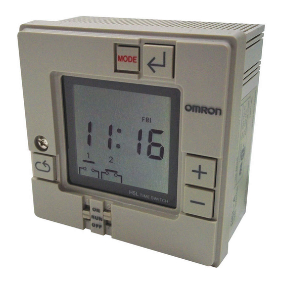
Daily Time Switch
H5L
Weekly Control with a Large Time Display
Easy Programming with Large Display and Interactive
Functions.
• Easy operation with five keys.
• Up to 24 steps of ON/OFF operations can be set.
• Power supply freely selectable from 100 to 240 VAC.
• Memory protection during power failure for up to 10 years.
• Certified for UL and CSA safety standards.
• The same setting can be used for multiple-day operation and
timer operation.
Refer to Safety Precautions for All Timers.
Refer to Safety Precautions on page 12
Ordering Information
Backup power supply function for memory
Screw terminals
Provided (approx. 10 years at 25°C)
Specifications
■ Time Ranges
Rated time
24 hrs x 7 days
■ Ratings
Rated supply voltage
Operating voltage range
Power consumption
Control outputs
protection
24 (Each ON or OFF is considered to be one step.) H5L-A
Time setting range
00:00 to 23:59
100 to 240 VAC (50/60 Hz)
85% to 110% of rated supply voltage
Approx. 4 VA at 240 VAC
15 A at 250 VAC, resistive load at 50°C
12 A at 250 VAC, resistive load at 55°C
Minimum applied load: 100 mA at 5 VDC (failure level: P, reference value)
96 mm
96 mm
For the most recent information on models that have been certified for
safety standards, refer to your OMRON website.
No. of program steps
Time division
1 min
CSM_H5L_DS_E_2_2
Model
1
Advertisement
Table of Contents

Related Manuals for Omron H5L


Summary of Contents for Omron H5L
-
Page 1: Ordering Information
Backup power supply function for memory No. of program steps Model protection Screw terminals Provided (approx. 10 years at 25°C) 24 (Each ON or OFF is considered to be one step.) H5L-A Specifications ■ Time Ranges Rated time Time setting range Time division... - Page 2 ■ Characteristics ±0.01% ±0.05 s max. (see note 1) Accuracy of operating time Setting error Influence of voltage Influence of temperature ±15 s per month (at 25°C) Time accuracy Insulation resistance 100 MΩ min. Dielectric strength 2,000 VAC, 50/60 Hz for 1 min (between current-carrying terminals and exposed non-current-carrying metal parts and between control power supply circuit and contact control output circuits) 1,000 VAC, 50/60 Hz for 1 min (between non-continuous contacts) Vibration resistance...
- Page 3 Nomenclature Mode Key Write Key Plus Key Note: This figure shows the LCD section with all display items Minus Key being displayed on the screen. Cycle Key Manual override switch Key Operation Name Function Mode Key Changes program mode Write Key To write the set data using the Plus and/or Minus Key.
- Page 4 4. Set "minute" using Plus and/or Minus Keys. Then press the Write Key to write the set minute. In the H5L, the cycle program can be used to repeat ON and OFF of output for a certain period in a predetermined cycle. A cycle program First...
- Page 5 Recovery after power failure Output 1 and 2 start Note: Refer to "Programming simultaneously Example". 3. The cycle period (from start time to stop time) does not need to be a multiple of the cycle frequency (ON time plus OFF time). The cycle period can be set within a range of 1 min to 24 hrs.
- Page 6 If the Write Key is pressed at this time, the step will be deleted. ■ LCD Display LCD Display (Display Example in Each Mode) Since the H5L employs interactive programming, the program mode and setting data are displayed on the LCD. Display Mode Display data...
- Page 7 To set the current time, "day of the week", "hour", and "minute" must be specified. First, turn on the power to the H5L. The contents of the memory are cleared on power-up and the TIM ADJ indicator is displayed as shown on the left.As an example, set the time to 11:15 on Tuesday.
- Page 8 To program the operation of the first circuit, "hour", "minute", and "output" must be specified. Press the Mode Key to place the H5L into PROG 1 mode. The display will be as shown on the left. Since the first circuit is to be turned ON at 7:40, set the "hour" to 7 by pressing the Plus or Minus Key and then store it in memory by using the Write Key.
- Page 9 We will now have to set the day of the week for the second circuit. 5. Second Circuit Day-of-the Week Setting Press the Mode Key to place the H5L into PROG 2, DAY WET mode. Initially, all days of the week are selected (shown by reverse video) and the SUN indicator will be flashing.
- Page 10 Dimensions Note: All units are in millimeters unless otherwise indicated. H5L-A 56.5 14.5 35.3 91.9 M3.5 terminal screws Dimensions Panel Cutout Mounting Bracket (Included) Dimensions 59.8 (See note 1) 68.5 (See note 2) Note: 1. When using mounting track PFP-100N or PFP-50N.
- Page 11 ■ Accessories (Order Separately) Front Cover Y92A-96A Mounting Track (Meets DIN EN 50022) PFP-100N/PFP-50N Note: 1. This dimension is 15 mm on both ends in the case of the PFP-100N but on one end in the case of the PFP-50N. (See note) (See note) (See note 2)
-
Page 12: Safety Precautions
Safety Precautions Refer to Safety Precautions for All Timers. Surface Mounting !CAUTION • Use a straight mounting bracket to surface mount the unit. Tighten terminal screws to the specified torque of approx. 0.8 N·m (maximum torque: 0.98 N·m). Loose screws may occasionally cause fires or malfunction. - Page 13 ALL DIMENSIONS SHOWN ARE IN MILLIMETERS. To convert millimeters into inches, multiply by 0.03937. To convert grams into ounces, multiply by 0.03527. In the interest of product improvement, specifications are subject to change without notice.
- Page 14 Warranty and Limitations of Liability WARRANTY OMRON's exclusive warranty is that the products are free from defects in materials and workmanship for a period of one year (or other period if specified) from date of sale by OMRON. OMRON MAKES NO WARRANTY OR REPRESENTATION, EXPRESS OR IMPLIED, REGARDING NON-INFRINGEMENT, MERCHANTABILITY, OR FITNESS FOR PARTICULAR PURPOSE OF THE PRODUCTS.
Need help?
Do you have a question about the H5L and is the answer not in the manual?
Questions and answers
How to close gate manually
To manually close the Omron H5L gate, use the front panel override switches to control the status of the outputs. Rotate the manual switch knob clockwise to manually turn ON the output.
This answer is automatically generated