Advertisement
Solid-state Timer
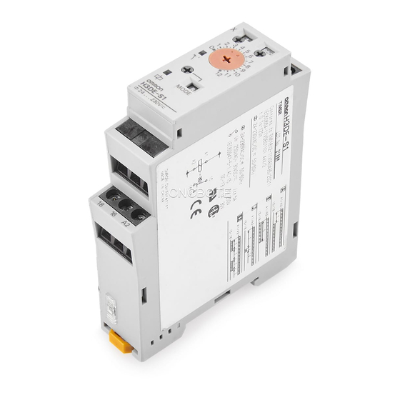
H3DE
DIN Track Mounted, Standard 22.5-mm Width Timer Range
• A wide AC/DC power supply range (24 to 230 VAC/DC) reduces the number of timer models kept in stock. (except for H3DE-H)
• 12-VDC model available for a specific application. (H3DE-M2)
• Nameplate provided for easy timer identification and management.
• Terminal clamp left open when delivered.
• Finger protection terminal block to meet VDE0106/P100.
• Enables easy sequence checks through instantaneous outputs for a zero set value at any time range.
• Incorporates environment-friendly, cadmium-free contacts. (except for H3DE-H)
• High immunity to inverter noise.
• Approved by UL and CSA.
• Conforms to EN61812-1 and IEC60664-1 4 kV/2 for Low Voltage, and EMC Directives.
■ Broad Line-up of H3DE Series
H3DE-M/S
Standard Timer
H3DE-M
H3DE-S
Solid-state Timer
H3DE-M/-S......................................................................................................................................
H3DE-F ...........................................................................................................................................
H3DE-G ..........................................................................................................................................
H3DE-H...........................................................................................................................................
Common to ALL Timers
Accessories.....................................................................................................................................
Precautions .....................................................................................................................................
H3DE
H3DE-F
Twin Timer
H3DE-F
Contents
H3DE-G
Star-delta Timer
H3DE-G
Solid-state Timer
H3DE-H
Power OFF-delay Timer
H3DE-H
B-53
B-63
B-69
B-75
B-81
B-82
H3DE
B-51
Advertisement
Table of Contents

Subscribe to Our Youtube Channel
Related Manuals for Omron H3DE


Summary of Contents for Omron H3DE
- Page 1 DIN Track Mounted, Standard 22.5-mm Width Timer Range • A wide AC/DC power supply range (24 to 230 VAC/DC) reduces the number of timer models kept in stock. (except for H3DE-H) • 12-VDC model available for a specific application. (H3DE-M2) •...
- Page 2 H3DE Solid-state Timer...
-
Page 3: Model Number Structure
(H3DE-S) cover a wide range of applications. • Programmable contact enables the building of a self-holding re- lay circuit (-@2 models). • A wide time setting range of 0.10 s to 120 h. Model Number Structure ■ Model Number Legend H3DE - 1. -
Page 4: Specifications
Note: 1. DC ripple rate: 20% max. 2. Since an inrush current of 0.25 A will occur when using the power supply voltage at 24 VDC, pay careful attention when turning on or off the power supply to the Timer with a solid-state output such as a sensor. - Page 5 Weight 120 g Note: 1. With the H3DE-M@, if the voltage exceeds 26.4 VAC/DC, the following hold at signal OFF for C, D, and G modes: Accuracy of operating time: 1% 50 ms max. at 1.2-s range Setting error: 10% +100/ 50 ms max.
-
Page 6: Block Diagram
(see note.) Note: When the output type selector switch on the bottom of the Timer is set to the instantaneous side, the relay R2 (terminal numbers 21/25, 22/ 26, and 24/28) becomes an instantaneous contact and turns ON/OFF in synchronization with the changes in the power supply. - Page 7 (DIN notation) (DIN notation) Note: 1. The relay R2 can be set to either instantaneous or time-limit contact using the switch located on the bottom of the Timer. 2. DC supply voltage does not require the designation of polarity. 3. The contact symbol for the H3DE is indicated with because it offers multiple operating modes and is different from the delayed contact for conventional timers.
-
Page 8: Operation
Turn the operating mode selector with a screwdriver until the desired operating mode (A, B, C, B2, D, E, J, or G for the H3DE-M and A, E, J, or B2 for the H3DE-S) appears in the operating mode display win- dow located below the selector. - Page 9 Note: 1. The minimum power reset time is 0.1 s and the minimum signal input time is 0.05 s. 2. The letter “t” in the timing charts stands for the set time and “t–a” means that the period is less than the time set.
- Page 10 Timer is in operation. Note: The start input of the H3DE-M1 or H3DE-M2 model is activated by applying a voltage to B1 and A2 terminals. The voltage can be applied by turning on the contact between B1 and A1 (Refer to Terminal Arrangement).
- Page 11 (Lit while Timer gives output.) Operating mode selector (select a mode from A, B, C, Operating mode display window B2, D, E, J, and G for the H3DE-M1/-M2, from A, E, J, and B2 for the H3DE-S1/S2) Power-on indicator (green) (Lit while the power is on.)
- Page 12 Dimensions Note: All units are in millimeters unless otherwise indicated. Terminal block (black) H3DE-M/-S Surface color: Light gray 5Y7/1 (OMRON) Output type selector switch (default setting: Time-limit output) Terminal block (black) H3DE-M/-S B-62 Solid-state Multi-functional Timer...
-
Page 13: H3De-F
• Independent ON- and OFF-time settings. Combinations of long ON- or OFF-time and short OFF- or ON- time setting are possible. • Long time range from 0.1 s to 12 h for both ON and OFF time settings. Model Number Structure ■... - Page 14 Conforms to EN61812-1, IEC60664-1 4 kV/2, VDE0106/P 100 Output category according to IEC60947-5-1 (AC-13; 250 V 5A/AC-15; 250 V 3 A/DC-13; 30 V 0.1 A) Note: Can be mounted to 35-mm DIN track with a plate thickness of 1 to 2.5 mm.
- Page 15 EN61000-4-2: 6 kV contact discharge (level 3) 8 kV air discharge (level 3) Immunity RF-interference from AM Radio Waves: EN61000-4-3: 10 V/m (80 MHz to 1 GHz) (level 3) Immunity Burst: EN61000-4-4: 2 kV power port and output port (level 3)
- Page 16 ■ I/O Function Inputs Outputs Control output Outputs are turned ON/OFF according to the time set by the ON-and OFF-time setting dial. ■ Terminal Arrangement (DIN notation) Note: DC supply voltage does not require the designation of polarity. H3DE-F...
-
Page 17: Time Setting
: OFF set time Note: 1. The reset time requires a minimum of 0.1 s. 2. When power is supplied in flicker-ON start mode, the OFF indicator lights momentarily. This, however, has no effect on the performance of the Timer. - Page 18 Nameplate for user use (20 x 5.4 mm white panel) Time scale display window ON-time unit display window Time unit selector Time scale selector (select one from s, 10s, min, or h for output ON) (select 0.1 or 1) Output ON indicator (orange) ON-time setting dial OFF-time setting dial...
-
Page 19: H3De-G
Solid-state Star-delta Timer H3DE-G • A wide star-time range (up to 120 seconds) and star-delta trans- fer time range (up to 0.5 seconds) Model Number Structure ■ Model Number Legend H3DE - 1. G: Star-delta timer Ordering Information ■ List of Models... - Page 20 Conforms to EN61812-1, IEC60664-1 4 kV/2, VDE0106/P100 Output category according to IEC60947-5-1 (AC-13; 250 V 5A/AC-15; 250 V 3 A/DC-13; 30 V 0.1 A) Note: Can be mounted to 35-mm DIN track with a plate thickness of 1 to 2.5 mm.
- Page 21 EN61000-4-2: 6 kV contact discharge (level 3) 8 kV air discharge (level 3) Immunity RF-interference from AM Radio Waves: EN61000-4-3: 10 V/m (80 MHz to 1 GHz) (level 3) Immunity Burst: EN61000-4-4: 2 kV power port and output port (level 3)
- Page 22 ■ I/O Functions Inputs Outputs Control output Star output is turned OFF when the dial set value is reached and delta output is ON after the preset transfer time elapses ■ Terminal Arrangement (DIN notation) Note: DC supply voltage does not require the designation of polarity.
-
Page 23: Time Unit Setting
Time Unit Setting Time Scale Selection The star-delta transfer time is set to 0.05, 0.1, 0.25 or 0.5 with the The star operation time scale selector on the upper-left side of the star-delta transfer time selector on the lower-right side of the front front panel can be set to 1 or 10 as a magnification. - Page 24 Dimensions Terminal block (black) H3DE-G Surface color: Light gray 5Y7/1 (OMRON) Terminal block (black) H3DE-G B-74 Solid-state Star-delta Timer...
-
Page 25: H3De-H
100 to 120 VAC H3DE-H H3DE-H 200 to 230 VAC 24 VAC/VDC 48 VAC/VDC Note: Specify both the model number and supply voltage when ordering. Example: H3DE-H 24 VAC/DC S Time span code Supply voltage ■ Accessories (Order Separately) Mounting Track 50 cm (l) x 7.3 mm (t) - Page 26 0.3 s minimum x 10 s 10 to 120 s Note: The Timer will not operate if the specified power-on time is not kept. Be sure to supply power for at least the period specified. ■ Ratings Rated supply voltage (see note)
- Page 27 4.5 kV (or 1.5 kV for 24/48 VAC/VDC models) (between current-carrying metal parts and exposed non-current- carrying metal parts) Noise immunity Square-wave noise generated by noise simulator (pulse width: 100 ns/1 s, 1-ns rise) 1.5 kV (between power supply terminals) Static immunity...
- Page 28 Control output The Timer operates instantaneously when the Timer is turned ON. The Timer is in counting operation after the Timer is turned OFF and the output of the Timer is turned OFF when the preset time elapses. ■ Terminal Arrangement (DIN notation) Note: DC supply voltage does not require the designation of polarity.
- Page 29 The operating time of the Timer is set with the time setting dial. of the S Series can be set to 0.1 or 1 and that of the L Series can be set to 1 or 10 as magnification coefficients.
- Page 30 Dimensions Terminal block (black) H3DE-H Surface color: Light gray 5Y7/1 (OMRON) Terminal block (black) H3DE-H B-80 Solid-state Power OFF-delay Timer...
-
Page 31: End Plate
Accessories (Order Separately) (Common) Note: The undermentioned is common for all H3DE models. Note: All units are in millimeters unless otherwise indicated. ■ Dimensions Mounting Track PFP-100N, PFP-50N PFP-100N2 7.3 0.15 29.2 35 0.3 27 27 0.15 35 0.3 25 15... -
Page 32: Precautions
When mounting the H3DE on a socket mounting track, hook portion input terminals without regarding polarity. (A) of the Timer to an edge of the track first, and then depress the With the H3DE only, a DC power supply must be connected to the Timer in the direction of (B). - Page 33 H3DE must be as short as possible and should not be installed alongside power lines. If the H3DE is influenced by inductive voltage that is 30% or more of the rated voltage, connect a CR filter with a capacitance of approximately 0.1 F and a resistance of approxi-...
- Page 34 230 VAC ALL DIMENSIONS SHOWN ARE IN MILLIMETERS. To convert millimeters into inches, multiply by 0.03937. To convert grams into ounces, multiply by 0.03527. In the interest of product improvement, specifications are subject to change without notice. Cat. No. L092-E1-05...
Need help?
Do you have a question about the H3DE and is the answer not in the manual?
Questions and answers