Table of Contents
Advertisement
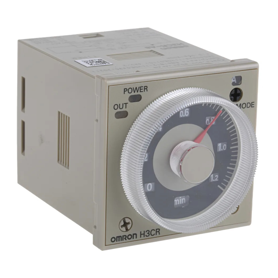
Solid-state Timer
H3CR
Please read and understand this catalog before purchasing the products. Please consult your OMRON representative if you have any questions
or comments. Refer to Warranty and Application Considerations (page 52), and Safety Precautions (page 22, 44, 51).
DIN 48 × 48-mm Multifunctional Timer Series
• Conforms to EN61812-1 and IEC60664-1 4 kV/2 for Low
Voltage, and EMC Directives.
• Approved by UL and CSA.
■ Broad Line-up of H3CR Series
H3CR-A
H3CR-A
H3CR-AS
11-pin model
H3CR-A8
8-pin model
H3CR-A8S
8-pin with
instantaneous
contact output
model
Note: H3CR-AS, H3CR-A8S: Transistor output models
Solid-state Timer
H3CR-A...........................................................................................................................................
H3CR-F ...........................................................................................................................................
H3CR-G ..........................................................................................................................................
H3CR-H ..........................................................................................................................................
Common to ALL Timers
Operation ........................................................................................................................................
Accessories.....................................................................................................................................
Safety Precautions ..........................................................................................................................
H3CR
H3CR-F
Twin Timer
H3CR-F
H3CR-FN
11-pin model
H3CR-F-300
H3CR-FN-300
H3CR-F8
H3CR-F8N
8-pin model
H3CR-F8-300
H3CR-F8N-300
Contents
• Lloyds/NK approvals.
• Six-language instruction manual provided.
H3CR-G
Star-delta Timer
8-pin model
Solid-state Timer
H3CR-H
Power OFF-delay Timer
H3CR-HRL
11-pin model
H3CR-H8L
8-pin model
H3CR-H8RL
2
24
30
37
45
47
51
H3CR
1
Advertisement
Table of Contents

Related Manuals for Omron H3CR


Summary of Contents for Omron H3CR
- Page 1 Solid-state Timer H3CR Please read and understand this catalog before purchasing the products. Please consult your OMRON representative if you have any questions or comments. Refer to Warranty and Application Considerations (page 52), and Safety Precautions (page 22, 44, 51).
-
Page 2: Model Number Legend
-AP models) Model Number Structure ■ Model Number Legend Note: This model number legend includes combinations that are not available. Before ordering, please check the List of Models on page 3 for avail- ability. H3CR-A@ @ @ - @ @ 1. -
Page 3: List Of Models
Ordering Information ■ List of Models Note: 1. Specify both the model number and supply voltage when ordering. Example: H3CR-A 100-240AC/100-125DC Supply voltage 2. The operating modes are as follows A: ON-delay D: Signal OFF-delay B: Flicker OFF start E: Interval... -
Page 4: Specifications
For PF085A Socket Y92H-8 Note: 1. Y92A-48G is a finger safe terminal cover which is attached to the P3G-08 or P3GA-11 Socket. 2. The Time Setting Ring and Panel Cover are sold together. 3. Hold-down Clips are sold in sets of two. - Page 5 60 to 600 ■ Ratings Rated supply voltage (See notes 1, 2, and 5.) 100 to 240 VAC (50/60 Hz)/100 to 125 VDC, 24 to 48 VAC (50/60 Hz)/12 to 48 VDC (24 to 48 VAC/VDC for H3CR- A8E) (See note3.)
- Page 6 IP40 (panel surface) Weight Approx. 90 g Note: 1. The value is ± 5% FS +100 ms to − 0 ms max. when the C, D, or G mode signal of the H3CR-AP is OFF. 2. Refer to the Life-test Curve. H3CR-A...
- Page 7 5,000 1,000 Reference: A maximum current of 0.15 A can be switched at 125 VDC (cosφ = 1) 30 VDC L/R = 7 ms and a maximum current of 0.1 A can be switched if L/R is 7 ms. In 250 VAC/30 VDC both cases, a life of 100,000 operations can be expected.
- Page 8 Power supply Oscillation Counting Output circuit circuit circuit circuit Indicator Reset input, start input, and gate input Input circuit circuit Power-ON Output-ON indicator indicator H3CR-AP Zero setting Time range/ Operating AC (DC) input detection...
- Page 9 OFF while the reset input is ON. Gate Prohibits time-measurement. Outputs Control output Outputs are turned ON according to designated output mode when preset value is reached. Note: H3CR-AP incorporates start input only. H3CR-A Solid-state Multi-functional Timer...
- Page 10 Note: Terminals 1, 3, 4, and 5 are empty. Terminals 2 and 7 are the same as for the H3CR-A8. H3CR-A8E (Contact Output) Power supply Note: Terminals 1, 3, 4, and 8 are empty. Terminals 2, 5, 6, 7, and 10 are the same as for the H3CR-A. H3CR-AP (Contact Output) Power supply Power supply Note: 1.
- Page 11 ■ Input Connections H3CR-A/-AS The inputs of the H3CR-A/-AS are no-voltage (short-circuit or open) inputs. No-voltage Inputs No-contact Input Contact Input No-contact Input (Connection to NPN open (Connection to a voltage collector output sensor.) output sensor.) 12 to 24 VDC...
- Page 12 H3CR-AP The start input of the H3CR-AP is voltage input. (Voltage imposition or open) Voltage Inputs No-contact Input No-contact Input Contact Input (Connection to PNP open (Connection to NPN open collector output sensor) collector output sensor) 12 to 24 VDC...
-
Page 13: H3Cr-A/-As/-Ap Timing Chart
2. The minimum input pulse width (for start, reset) is 0.05 s. 3. The letter “t” in the timing charts stands for the set time and “t–a” means that the period is less than the time set. 4. Power supply start in mode J is also possible for H3CR-A8/-A8E/-A8S/-A8-301 models. - Page 14 Start Gate Reset Output relay Note: 1. This timing chart indicates the gate input in op- erating mode A (ON-delay operation). 2. The set time is the sum of t and t 3. H3CR-AP model incorporates start input only. H3CR-A...
- Page 15 Note: 1. The minimum power-opening time (“Rt”) is 0.1 s. 2. The letter “t” in the timing charts stands for the set time and “t–a” means that the period is less than the time set. H3CR-A Solid-state Multi-functional Timer...
- Page 16 Power indicator Note: 1. The minimum power-opening time (“Rt”) is 0.1 s. 2. The letter “t” in the timing charts stands for the set time and “t–a” means that the period is less than the time set. H3CR-A Solid-state Multi-functional Timer...
- Page 17 Operating mode display window Operating mode selector Select a mode from: Output indicator (orange) A, B, B2, C, D, and E (H3CR-A, -AP, and -AS) (Lit when output) A, B2, E and J (H3CR-A8, -A8S, and -A8E) G and J (H3CR-A-300)
- Page 18 H3CR-AS H3CR-A8@ 98.5 89.9 87.6 H3CR-AS H3CR-AP 100.8 H3CR-AP Adapter Adapter P3G-08 P3GA-11 Y92F-30 Y92F-30 (When (When Y92A-48G Y92A-48G P2CF-11 P2CF-08 mounted) mounted) P2CF-11-E P2CF-08-E These dimensions vary with the kind of DIN track (reference value). H3CR-A Solid-state Multi-functional Timer...
-
Page 19: B/B2 Mode: Flicker
B/B2 Mode: Flicker the Timer. The flicker operation in the B and B2 modes can be effectively applied to lamp or buzzer (ON and OFF) alarms or the monitoring of Power (2 and 10) an intermittent operation with a display. -
Page 20: C Mode: Signal On/Off-Delay
1. Power-ON Start/Instantaneous Operation/ 1. Power-ON Start/Instantaneous Operation/ Time-limit Reset Time-limit Reset A set of these functions is useful for the operation of a machine for a specified period when power is ON. Power (2 and 10) Start (2 and 6) - Page 21 2. Signal Start/Instantaneous Operation/ 2. Signal Start/Instantaneous Operation/ Time-limit Reset Time-limit Reset This function is useful for the repetitive control such as the filling of liquid for a specified period after each Signal start input. Power (2 and 10) Start (2 and 6)
- Page 22 H3CR-A cuiting due to a sneak current to the transformerless power supply. If 5, 6, 7 a relay or transistor is connected to two or more Timers, the input ter- Input terminal minals of those Timers must be wired properly so that they will not...
- Page 23 Relationship between Input and Power If a relay or transistor is connected to two or more Timers, the input terminals of those Timers must be wired properly so that they will not Supply Circuits (H3CR-A@/-A@S) be different in phase or the terminals will be short-circuited to one another (refer to the figures below).
- Page 24 ON- or OFF-time and short OFF- or ON-time set- tings are possible. • Fourteen time ranges from 0.05 s to 30 h or from 1.2 s to 300 h depending on the model to be used. • Models with a flicker ON start or flicker OFF start are available.
- Page 25 For PL08 and PL11 Sockets Y92H-7 For PF085A Socket Y92H-8 Note: 1. Y92A-48G is a finger safe terminal cover which is attached to the P3G-08 or P3GA-11 Socket. 2. Hold-down Clips are sold in sets of two. Specifications ■ General...
- Page 26 Note: 1. A power supply with a ripple of 20% max. (single-phase power supply with full-wave rectification) can be used with each DC Model. 2. Do not use an inverter output as the power supply. Refer to Power Supplies in Safety Precautions for All Timers on page 51 for details.
- Page 27 5,000 1,000 Reference: A maximum current of 0.15 A can be switched at 125 VDC (cosφ = 1) 30 VDC L/R = 7 ms and a maximum current of 0.1 A can be switched if L/R is 7 ms. In 250 VAC/30 VDC both cases, a life of 100,000 operations can be expected.
- Page 28 Output Output Note: 1. The reset time requires a minimum of 0.1 s. 2. When power is supplied in flicker ON start mode, the OFF indicator lights momentarily. This, however, has no effect on the performance of the Timer. Nomenclature...
- Page 29 H3CR-F8 H3CR-FN H3CR-F8N 92.3* 90.0 103.2* 100.9 H3CR-F H3CR-F8 H3CR-FN H3CR-F8N P3GA-11 P3G-08 Y92F-30 Y92F-30 (When (When Y92A-48G Y92A-48G P2CF-11 P2CF-08 mounted) mounted) P2CF-11-E P2CF-08-E These dimensions vary with the kind of DIN track (reference value). H3CR-F Solid-state Twin Timers...
- Page 30 Solid-state Star-delta Timer H3CR-G DIN 48 × 48-mm Star-delta Timer • A wide star-time range (up to 120 seconds) and star-delta trans- fer time range (up to 0.5 seconds). Model Number Structure ■ Model Number Legend H3CR - G 8 @ L @ 1 2 3 4 5 1.
- Page 31 For PF085A Socket Y92H-2 Note: 1. Y92A-48G is a finger safe terminal cover which is attached to the P3G-08 Socket. 2. The Time Setting Ring and Panel Cover are sold together. 3. Hold-down Clips are sold in sets of two.
- Page 32 Control outputs Note: 1. Do not use an inverter output as the power supply. Refer to Power Supplies in Safety Precautions for All Timers on page 51 for details. 2. Refer to Power Supplies in Safety Precautions for All Timers on page 51 when using the Timer together with a 2-wire AC proximity sensor.
- Page 33 5,000 1,000 Reference: A maximum current of 0.15 A can be switched at 125 VDC (cosφ = 1) 30 VDC L/R = 7 ms and a maximum current of 0.1 A can be switched if L/R is 7 ms. In both cases, a life of 100,000 operations can be expected.
- Page 34 Outputs Control output If the time reaches the value set with the time setting knob, the star operation output will be turned OFF and there will be delta operation output after the set star-delta transfer time has elapsed. ■ Terminal Arrangement...
- Page 35 Star-delta transfer time selector Star operation time range selector (select one from 0.05 s, 0.1 s, (select one from 6, 12, 60, and 120 0.25 s, and 0.5 s) at full scale) Star-delta transfer time display window...
- Page 36 Dimensions with Front Connecting Socket Dimensions with Back Connecting Socket P2CF-08-@ P3G-08 92.9 86.4 H3CR-G8@L 101.3* H3CR- G8@L P3G-08 Y92F-30 (When Y92A-48G P2CF-08 mounted) P2CF-08-E These dimensions vary with the kind of DIN track (reference value). H3CR-G Solid-state Star-delta Timer...
- Page 37 • 11-pin and 8-pin models are available. Model Number Structure ■ Model Number Legend Note: This model number legend includes combinations that are not available. Before ordering, please check the List of Models on page 37 for availability. H3CR - H @ @ L @ @ 3 4 5 1.
- Page 38 Note: 1. If the above minimum power ON time is not secured, the H3CR may not operate. Be sure to secure the above minimum power ON time. 2. Do not use the Timer with a repeat period of less than 3 s. Doing so may result in abnormal heating or burning. Refer to Safety Precautions (H3CR-H) on page 44 for details.
- Page 39 ■ Ratings Rated supply voltage (See notes 1 and 2.) 100 to 120 VAC (50/60 Hz), 200 to 240 VAC (50/60 Hz), 24 VAC/VDC (50/60 Hz), 48 VDC, 100 to 125 VDC Operating voltage range 85% to 110% of rated supply voltage 1 k Ω...
- Page 40 Turns off the control output and resets the elapsed time. Outputs Control output Operates instantaneously when the power is turned on and time-limit resets when the set time is up after the power is turned off. H3CR-H Solid-state Power OFF-delay Timer...
- Page 41 ■ Terminal Arrangement Note: DC models, including 24 VAC/DC models, have polarity. 8-pin Models Without Reset Input (H3CR-H8L) With Reset Input (H3CR-H8RL) Reset input Power supply Power supply Note: Leave terminal 3 open. Do not use them as relay terminals.
- Page 42 ■ Timing Chart Set time Rt: Minimum power ON time (S-series: 0.1 s min.; M-series: 2 s min.) If the power ON time is less than this value, the Timer may not operate (i.e., output may not turn ON). Model Timing chart...
- Page 43 112.2* 109.9 H3CR- H3CR-HRL H8@L P3GA-11 P3G-08 Y92F-30 Y92F-30 (When (When Y92A-48G Y92A-48G P2CF-08 P2CF-11 mounted) mounted) P2CF-08-E P2CF-11-E These dimensions vary with the kind of DIN track (reference value). H3CR-H H3CR-H Solid-state Power OFF-delay Timer Solid-state Power OFF-delay Timer...
- Page 44 If it is required that the output be turned on repeatedly with an inter- Do not attempt to connect any input terminal to any terminal other val of shorter than 3 s, consider use of the H3CR-A in mode D (signal than the input terminal or to apply voltage across other than the OFF-delay).
- Page 45 ■ Basic Setting • H3CR-F Twin Timers A time range (0 to 1.2, 0 to 3, 0 to 12, or 0 to 30) is selected for ON- and OFF-time using the time range selector at the lower left corner of...
- Page 46 A star operation time range (0 to 6, 0 to 12, 0 to 60, or 0 to 120 A time range (0 to 0.6, 0 to 1.2, 0 to 6, and 0 to 12) is selected with seconds) is selected with the star operation time range selector at the time range selector at the lower left corner of the front panel.
- Page 47 Flush Mounting Adaptor Panel Back Connecting Socket Y92F-30 Panel Cutout Note: The adapters for two or more timers mounted in a vertical line are different in 0.5 R max. +0.6 −0 orientation from those mounted in a horizontal line. N can be obtained as follows (n: the number of H3CR models arranged side by side) Without a Cover: N = (48n - 2.5)
- Page 48 35.4 Terminal Arrangement/ Two, 4.5 dia. Internal Connections holes (Top View) Surface Mounting Holes 50 max. Two, 4.5 dia. or two, M4 20.3 max. P2CF-08-E (Finger Safe Terminal Type) Conforming to VDE0106/P100 40±0.2 Eight, M3.5 × 7.5 sems 70 max.
- Page 49 27±0.15 35±0.3 15 25 25 15 15 25 15 (5) 1,000 1,000 (500) (See note) (See note) Note: The value shown in parentheses are for the PFP-50N. End Plate Spacer PFP-M PFP-S 35.5 35.3 34.8 44.3 11.5 M4 x 8 pan head 16.5...
- Page 50 Time Setting Ring/Panel Cover for H3CR-A/-G There are three types of Panel Covers (Y92P-48GL, Y92P-48GB, The Time Setting Ring and Panel Cover should be used as a pair. and Y92P-48GM), all of which are available in three colors. Use the...
- Page 51 H3CR-F models at the lowest selector setting. Doing so may result in damage to contacts. Power Supplies A DC power supply can be connected if its ripple factor is 20% or less and the mean voltage is within the rated operating voltage range of the Timer.
-
Page 52: Warranty And Application Considerations
CONTRACT, WARRANTY, NEGLIGENCE, OR STRICT LIABILITY. In no event shall the responsibility of OMRON for any act exceed the individual price of the product on which liability is asserted. IN NO EVENT SHALL OMRON BE RESPONSIBLE FOR WARRANTY, REPAIR, OR OTHER CLAIMS REGARDING THE...
Need help?
Do you have a question about the H3CR and is the answer not in the manual?
Questions and answers