Table of Contents
Advertisement
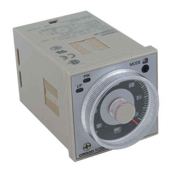
Solid-state Timer
H3BA-N
Please read and understand this catalog before purchasing the products.
Please consult your OMRON representative if you have any questions or
comments. Refer to Warranty and Application Considerations (page 20),
and Safety Precautions (page 16).
Solid-state Timer with Valuable Multiple-time
Ranges and Multiple-operating Modes
• Handles a wide range of applications through six operating
modes.
• With H3BA-N8H models, the output type can be switched
between time-limit DPDT and time-limit SPDT + instantaneous
SPDT using a selector.
• Setting rings (order separately) to enable consistent settings
and to limit the setting range.
• Panel Covers (order separately) to enable various panel
designs.
• Conforms to LR and approved by UL and CSA.
■ Broad Line-up of H3B@-N Series
H3BA-N
Multi-functional Timer
H3BA-N
11-pin model
8-pin with
H3BA-N8H
instantaneous
contact output
and time-limit
output
Note: Refer to the H3BF-N/BG-N/BH-N Datasheet (Cat. No. L094-E1-1) for details.
H3B@-N
H3BF-N
Twin Timer
H3BF-N8
8-pin model
H3BG-N
Star-delta Timer
H3BG-N8
8-pin model
8-pin with
H3BG-N8H
instantaneous
contact output
Solid-state Timer
RC
H3BH-N
Power OFF-delay Timer
H3BH-N8
8-pin model
H3BA-N
1
Advertisement
Table of Contents


Need help?
Do you have a question about the H3BA-N and is the answer not in the manual?
Questions and answers
Is it possible to have an automatic reset or do you have to have a switch to reset timer?
The Omron H3BA-N timer requires a switch for resetting. It uses a start/reset input (e.g., pin No. 2) to reset the timer, which operates when a transistor or relay is turned ON. There is no mention of an automatic reset feature.
This answer is automatically generated