Advertisement
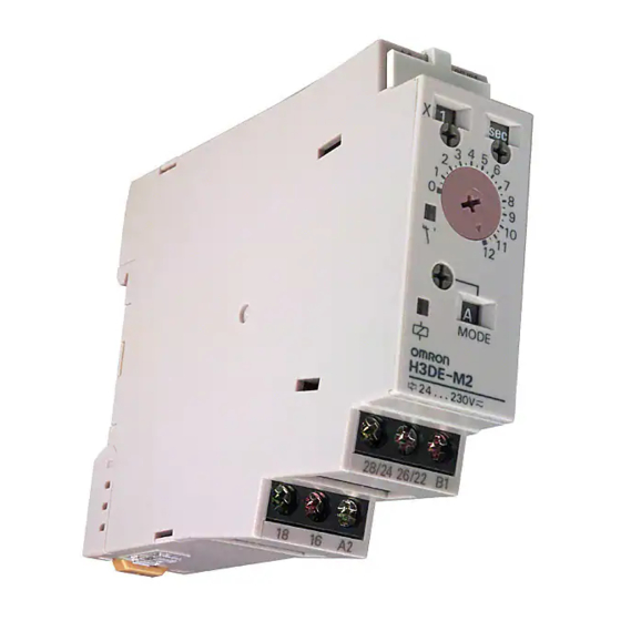
Multifunction Timer
Analog Set Multifunction Timers
In Slim 22.5 mm Design
For Track Mounting
Wide AC/DC power supply range
H
(24 to 230 VAC/DC) minimizes inventory
12 VDC available in H3DE-M model
H
Programmable contacts (available in
H
-M2 and -S2 models) can enable and
disable a self-holding relay circuit
Eight operating modes in the H3DE-M
H
(four in the H3DE-S) offer wide
application flexibility
Time setting range 0.10 sec to 120 hrs
H
Finger protection terminal block
H
Ordering Information
J TIMER
Description
Contact output
DPDT (time-limit output SPDT);
and switchable SPDT
(time-limit ←→ instantaneous)
(time-limit ←→ instantaneous)
SPDT (time-limit output SPDT)
J MODEL NUMBER LEGEND
H3DE-j-j-j
1. M: Multifunction type
S: Standard type
1
2 3
J ACCESSORIES (ORDER SEPARATELY)
Item
Mounting track
End plate
Spacer
Part number
Supply voltage
Multifunctional
12 VDC
H3DE-M2 DC12
24 to 230
H3DE-M2 AC/DC24-230
VAC/DC
H3DE-M1 AC/DC24-230
2. 1: SPDT
2: DPDT
Description
50 cm (l) x 7.3 mm (t)
1 m (l) x 7.3 mm (t)
1 m (l) x 16 mm (t)
H3DE
Standard
—
H3DE-S2 AC/DC24-230
H3DE-S1 AC/DC24-230
3. Supply voltage
Part number
PFP-50N
PFP-100N
PFP-100N2
PFP-M
PFP-S
Advertisement
Table of Contents

Subscribe to Our Youtube Channel
Related Manuals for Omron H3DE-M2


Summary of Contents for Omron H3DE-M2
- Page 1 J TIMER Description Part number Contact output Supply voltage Multifunctional Standard DPDT (time-limit output SPDT); 12 VDC H3DE-M2 DC12 — and switchable SPDT (time-limit ←→ instantaneous) (time-limit ←→ instantaneous) 24 to 230 H3DE-M2 AC/DC24-230 H3DE-S2 AC/DC24-230 VAC/DC SPDT (time-limit output SPDT)
-
Page 2: Specifications
Note: When the main dial is set to “0” for all settings, the output will operate instantaneously. J RATINGS Rated supply voltage 24 to 230 VAC/DC (50/60 Hz) (See Notes 1 and 2.) 12 VDC (H3DE-M2 model only) Operating voltage range 85% to 110% of rated supply voltage Power reset Minimum power-off time: 0.1 s Reset voltage 2.4 VAC/DC max. - Page 3 H3DE H3DE J CHARACTERISTICS Accuracy of operating time ±1% max. of FS (±1% ±10 ms max. at 1.2-s range) (See Note 1.) Setting error ±10% ±50 ms max. of FS (See Note 1.) Signal input time 50 ms min. (See Note 1.) Voltage influence ±0.5% max.
-
Page 4: Front View
(Lit while the power is on.) Bottom View Output Type Selector Switch Settings Setting Output type Time-limit output (terminal numbers 25, 26 and 28) (default setting) Output type selector switch for H3DE-M2/-S2 (default setting Instantaneous output is time-limit output) (terminal numbers 21, 22 and 24) -
Page 5: Operation
H3DE H3DE Operation J BLOCK DIAGRAM H3DE-M1/-M2 Zero setting Time range/ Operating AC (DC) input detection unit selectors mode selector circuit Oscillation Power supply Counting Output circuit circuit circuit circuit Indicator Start input Input circuit circuit Power-ON Output indicator indicator H3DE-S1/-S2 Zero setting Time range/... -
Page 6: Operating Mode Selection
H3DE H3DE J BASIC OPERATION Time Unit and Time Scale Selection The desired time unit (sec, min, hrs, or 10h) can be displayed in Selector Setting the time unit display window above the time setting dial by The selectors can be turned clockwise and counterclockwise to turning the time unit selector located at the upper right corner of select the desired time unit, time scale, or operating mode. - Page 7 Note: The start input of the H3DE-M1 or H3DE-M2 model is activated by applying a voltage to B1 and A2 terminals. The voltage can be applied by turning on the contact between B1 and A1 (Refer to Terminal Arrangement).
- Page 8 Timer is in operation. Note: The start input of the H3DE-M1 or H3DE-M2 model is activated by applying a voltage to B1 and A2 terminals. The voltage can be applied by turning on the contact between B1 and A1 (Refer to Terminal Arrangement).
-
Page 9: Installation
H3DE H3DE Dimensions Unit: mm (inch) J H3DE-M H3DE-S Terminal block (black) Surface color: 5Y7/1 (OMRON) 22.5 (0.89) 12.7 (3.94) 7° (2.95) (3.11) 7° 36.9 Output type selector switch (default setting: Time-limit output) Terminal block (black) Installation J TERMINAL ARRANGEMENT Note: 1. -
Page 10: Contact Input
H3DE H3DE J INPUT CONNECTIONS The inputs of the H3DE-M1/-M2 are voltage (voltage imposition or open) inputs. No-Contact Input No-Contact Input Contact Input Connection to PNP output sensor. Connection to NPN output sensor. Sensor Timer Timer Timer 24 VDC (- -) Start Start 24 VDC... - Page 11 H3DE H3DE Accessories (Order Separately) Unit: mm (inch) J DIMENSIONS Mounting Track PFP-100N, PFP-50N PFP-100N2 7.3±0.15 35±0.3 27 29.2 27±0.15 35±0.3 25 15 L: Length PFP-100N 39.37 in 19.69 in PFP-50N 50 cm 39.37 in PFP-100N2 Spacer PFP-S End Plate PFP-M (0.63) 34.8 35.3...
- Page 12 H3DE H3DE J POWER SUPPLIES J MOUNTING CLEARANCE The H3DE Series is provided with a transformerless power If the load current is continuously being supplied to the Timer for supply system. An electric shock may be received if the input a long period of time, be sure to provide the mounting clearance terminal or the output type selector switch is touched while power as shown in the figure below.
- Page 13 H3DE H3DE J INPUT/OUTPUT J INPUT WIRES Relationship between Input and The input wires must be as short as possible. If the floating Power Supply Circuits capacity of wires exceeds 2,000 pF (approx. 17 m for cables with 120 pF/m), the operation will be affected. Pay particular attention when using shielded cables.
- Page 14 NOTE: DIMENSIONS SHOWN ARE IN MILLIMETERS. To convert millimeters to inches divide by 25.4. OMRON ON- -LINE OMRON ELECTRONICS LLC OMRON CANADA, INC. One East Commerce Drive 885 Milner Avenue Global - - http://www.omron.com Schaumburg, IL 60173 Scarborough, Ontario M1B 5V8 USA - - http://www.omron.com/oei 1-800-55-OMRON 416-286-6465 Canada - - http://www.omron.com/oci...
Need help?
Do you have a question about the H3DE-M2 and is the answer not in the manual?
Questions and answers