
Subscribe to Our Youtube Channel
Related Manuals for Vivo STAND-TV03E2


Summary of Contents for Vivo STAND-TV03E2
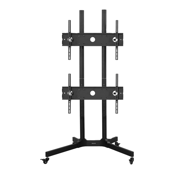
- Page 1 Dual Screen Mobile TV Cart SKU: STAND-TV03E2 Instruction Manual Assembly Video & Product Info www.vivo-us.com/products/stand-tv03e2...
- Page 2 If you do not understand these directions, or if you have any doubts about the safety of the installation, please contact our product support team at 309-278-5303 or help@vivo-us.com for further assistance. Check carefully to make sure there are no missing or defective parts. Improper installation may cause damage or serious injury. Do not use this product for any purpose that is not explicitly specified in this manual.
-
Page 3: Package Contents
Package Contents A (x2) B (x2) C (x1) Long Foot Short Foot Base w/Cover D (x2) E (x2) F (x2) Grommet Lower Pole Top Pole Cover G (x2) H (x4) I (x4) Pole Connector Pole Cover Caster J (x4) K (x4) L (x2) Universal Plate Plastic Spacer... -
Page 4: Included Hardware & Tools
Included Hardware & Tools S-A (x8) S-B (x4) S-C (x18) S-D (x2) M-A (x8) M6x60mm M6 Socket M6x10mm M5x6mm Set M4x12mm Screw Plate Screw Screw Screw M-B (x8) M-C (x8) M-D (x8) M-E (x8) M-F (x8) M4x30mm M6x20mm M6x35mm M8x20mm M8x35mm Screw Screw... -
Page 5: Assembly Steps
ASSEMBLY STEPS STEP 1 Attach Casters (I) to Long Feet (A) and Short Feet (B) using Wrench (T-D). STEP 2 Separate Base w/Cover (C) into Base (C1) and Cover (C2). - Page 6 STEP 3 Attach Long and Short Legs (A, B) to Base (C1) using M6x60mm Screws (S-A), Threaded Plates (S-B), and 5mm Allen Wrench (T-C). Back S-A (x8) Front NOTE: Short Legs (B) should be on the same side as the large holes on on Base (C1), indicated by the arrow above.
- Page 7 Slide Cover (C2) over Lower Poles (E) and onto Base (C1). To ensure a correct fit, make sure side with logo is facing the front. NOTE: The front of the Cover is Front marked with the VIVO logo. Ensure this is facing the front. Back...
- Page 8 STEP 7 Thread Top Poles (F) onto Pole Connectors (G). STEP 8 Slide Universal Plate Connectors (J) and Plastic Spacers (K) onto Top Poles (F) and tighten the set screw using 4mm Allen Wrench (T-B). Connect and install Pole Covers (H) onto Top Poles. Do not fully tighten screws Secure Plastic Spacers (K) to Plate Connectors (J).
- Page 9 STEP 9 Assemble Universal Plates (L) to Universal Plate Connectors (J) with M6x10mm Screws (S-C) and M6 Washers (M-I). Tighten using 4mm Allen Wrench (T-B). Do not fully tighten screws. S-C (x16) M-I (x16)
- Page 10 STEP 10 1). Clip Level (T-E) onto Universal Plate (L). 2). Adjust the level of Universal Plate (L) by loosening the set screw in the back of Universal Plate Connectors (J) using 4mm Allen Wrench (T-B). 3). Tighten the set screws again once you’ve reached desired height and level.
- Page 11 STEP 11 Lift the Cover (C2) up. Tighten the previously installed M6x10mm Screws (S-C) using 4mm Allen Wrench (T-B). Install the M5x6mm Set Screws (S-D) using the 2.5mm Allen Wrench (T-A). S-D (x2)
- Page 12 STEP 12 Secure Right VESA Bracket (M) and Left VESA Bracket (N) to the back of your television using Screws (M-A through M-G) and Washers (M-H through M-J), depending on the size of the mounting holes on the television. For curved or recessed TVs, Spacers (M-K through M-M) may be required. Loosen Security Screw on both VESA Brackets with 5mm Allen Wrench (T-C) for easy mounting.
- Page 13 STEP 13 Place TV with VESA Brackets onto Universal Plate (L). Tighten the Security Screws on the bottom of the installed VESA Brackets using 5mm Allen Wrench (T-C) to secure the television to the stand. Security Screw...
- Page 14 STEP 14 Install Grommet Covers (D) into Lower Poles (E). Cables can be inserted into the tops of Pole Covers (H) and be routed out the back using either the Cable Slots in the back of Lower Poles (E) or through the bottom of the Base (C). Cable Slots...
- Page 15 Leveling If additional leveling and height adjustment is required after television is attached, follow the steps below. NOTE: TV’s should be removed before leveling the Universal Plate. 1). Clip Level (T-E) onto Universal Plate (L). 2). Adjust the level of Universal Plate (L) by loosening the set screw in the back of Universal Plate Connectors (J) using 2.5mm Allen Wrench (T-A).
- Page 16 LAST UPDATED: 11/17/2023 REV2 v2.0 Need Help? Get In Touch Monday-Friday from 7:00am-7:00pm CST help@vivo-us.com www.vivo-us.com 309-278-5303 Chat live with an agent! FOR MORE GREAT VIVO PRODUCTS, CHECK OUT OUR WEBSITE AT: WWW.VIVO-US.COM VIVO-us @vivo_us...
Need help?
Do you have a question about the STAND-TV03E2 and is the answer not in the manual?
Questions and answers