Lowrance HDS Carbon Quick Start Manual
Hide thumbs
Also See for HDS Carbon:
- Operator's manual (258 pages) ,
- Installation manual (88 pages) ,
- Quick start manual (9 pages)
Table of Contents
Advertisement
Quick Links
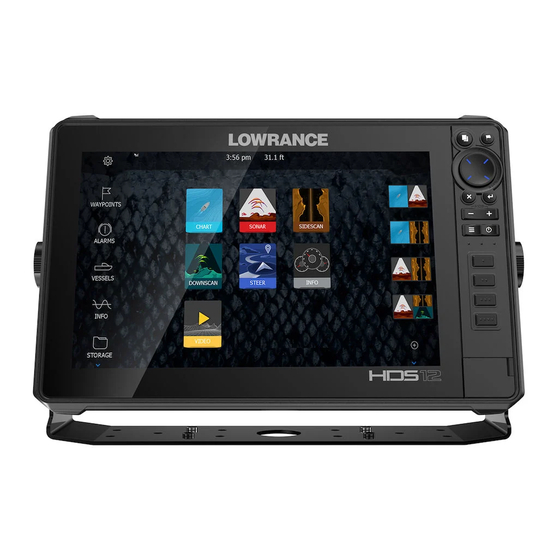
Overview
1
No. Key
1
Touchscreen
2
Pages key
3
Cursor keys
Zoom out/
4
Zoom in keys
5
Exit (X) key
6
Menu key
7
Waypoint key
8
Enter key
9
Panel key
10
Power key
Card reader door
11
microSD card readers
12
988-11255-001 EN 1/4
HDS Carbon
Quick Start Guide
Function
Activates the home page
Pans the cursor, moves through menu items and adjusts values
Zooms the screen; press keys simultaneously to save a Man
Overboard (MOB) waypoint
Exits dialogs, returns user to the previous menu level and removes
the cursor from the screen
Activates the panel menu; press twice to access the Settings
menu; press and hold to hide the panel menu
Opens the new waypoint dialog; press twice to save a waypoint;
press and hold to access the Find menu
Confirms selections and saves settings
Switches the active panel on a multiple-panel display; press and
hold to expand the active panel to a full-page panel
Opens the System Controls dialog, adjusts the backlight level and
powers the unit on/off
4
5
6
7
HDS Carbon |
Quick Start Guide - EN
EN
2
3
8
9
10
11
12
| 1
Advertisement
Chapters
Table of Contents

Related Manuals for Lowrance HDS Carbon


Summary of Contents for Lowrance HDS Carbon
- Page 1 Opens the System Controls dialog, adjusts the backlight level and Power key powers the unit on/off Card reader door microSD card readers 988-11255-001 EN 1/4 HDS Carbon | Quick Start Guide - EN...
- Page 2 Adjust splits Allows user to adjust panel size when multiple panels are displayed Data overlay Turns on/off data overlay display Edit overlay Allows editing of the size, position and content of overlay data HDS Carbon | Quick Start Guide - EN...
-
Page 3: Device Configuration
When you start up the unit for the first time, or after restoring defaults, the configuration dialog appears. Configure this device Select to use the configuration wizard to configure the unit and other networked devices. Close Select to manually configure settings. HDS Carbon | Quick Start Guide - EN... - Page 4 Selecting pages Tap the page icon Accessing quick splitscreen pages (quick splits) Press and hold the page icon Customizing favorite pages Several panel configurations are available: HDS Carbon | Quick Start Guide - EN...
- Page 5 ¼ Note: Menu You can also press and hold the key for three seconds to hide a page menu. The menu is restored by pressing the Menu key. Settings menu Data overlay HDS Carbon | Quick Start Guide - EN...
- Page 6 Tap the screen or press the Cursor keys to activate the cursor. Drag your finger in any Clear Cursor Exit direction to pan the screen. Select or press the key to remove the cursor from the page. Multi-touch zooming HDS Carbon | Quick Start Guide - EN...
- Page 7 Press the dedicated waypoint key twice to quickly save a waypoint. Sonar Adjusting sonar settings Sensitivity and Colorline are adjusted by dragging the slide bar vertically. The slide bar is Sensitivity Colorline accessed by tapping on the Sonar menu. HDS Carbon | Quick Start Guide - EN...
-
Page 8: Viewing Sonar History
Selecting a sonar frequency ¼ Note: StructureScan® frequencies (800 kHz and 455 kHz) are selected from the Structure page frequency menu. HDS Carbon | Quick Start Guide - EN... - Page 9 HDS Carbon Operator Manual ENGLISH www.lowrance.com...
- Page 11 Copyright© 2012 Fishing Hot Spots. ™ ™ FUSION-Link Marine Entertainment Standard is a registered trademark of FUSION Electronics Ltd. ® C-MAP is a registered trademark of C-MAP. ® FLIR is a registered trademark of FLIR. Preface | HDS Carbon Operator Manual...
- Page 12 StructureScan® HD (StructureScan HD) Copyright Copyright © 2016 Navico Holding AS. Warranty The warranty card is supplied as a separate document. In case of any queries, refer to the brand website of your display or system: www.lowrance.com. Preface | HDS Carbon Operator Manual...
- Page 13 If you are unsure, contact your service provider to confirm rates and restrictions. About this manual This manual is a reference guide for operating the HDS Carbon. It assumes that all equipment is installed and configured, and that the system is ready to use.
- Page 14 The manuals can be read from a card inserted in the card reader or copied to the unit’s internal memory. Use the menu options or the keys and on-screen buttons to maneuver in the PDF file as described below: • Search, Goto page, Page Up and Down Preface | HDS Carbon Operator Manual...
- Page 15 The software version currently on this unit can be found in the About dialog. The About dialog is available in the System Settings. For more information, refer to "About" on page 172. For upgrading your software, refer to "Software upgrades" on page 180. Preface | HDS Carbon Operator Manual...
- Page 16 Preface | HDS Carbon Operator Manual...
-
Page 17: Table Of Contents
Panning the chart Vessel symbol Chart scale Positioning the vessel on the chart panel Displaying information about chart items Using the cursor on the chart panel Creating routes Find objects on chart panels 3D charts Contents | HDS Carbon Operator Manual... - Page 18 Viewing the recorded sounder data Sonar view options Sonar settings 82 StructureScan The StructureScan image Zooming the StructureScan image Using the cursor on the StructureScan panel Viewing StructureScan history Setting up the StructureScan image Stop sonar Contents | HDS Carbon Operator Manual...
- Page 19 104 Safe operation with the autopilot 104 Switching from automatic navigation to standby mode 105 Autopilot interface 106 Autopilot control of the trolling motor 109 Autopilot settings 112 Outboard motor autopilot 112 Safe operation with the autopilot Contents | HDS Carbon Operator Manual...
- Page 20 146 Searching for AIS items 146 Viewing information about single AIS targets 147 AIS information on radar panels 147 Calling an AIS vessel 148 AIS SART 149 Vessel alarms 150 Vessel settings 153 Audio 153 Enabling audio Contents | HDS Carbon Operator Manual...
- Page 21 170 Alarms 170 Settings 174 Vessels 174 Sun, Moon 174 Trip calculator 174 Files 174 Find 175 GoFree Shop 176 Alarms 176 Alarm system 176 Type of messages 176 Single alarms 176 Multiple alarms Contents | HDS Carbon Operator Manual...
- Page 22 177 Acknowledging a message 177 Alarms dialog 179 Maintenance 179 Preventive maintenance 179 Checking the connectors 179 Touchscreen calibration 179 NMEA Data logging 180 Software upgrades 182 Backing up your system data 185 Touchscreen operation Contents | HDS Carbon Operator Manual...
-
Page 23: Introduction
Key: Use the cursor keys to select an item, confirm by pressing the Enter key. Use the cursor keys to select a new position, and then press the Enter key again to confirm the new position. Introduction | HDS Carbon Operator Manual... -
Page 24: The Front Panel And Keys
Menu key A single press displays the menu for the active panel/ overlay. Press and hold to hide or show the menu. A quick double-press displays the settings menu. Introduction | HDS Carbon Operator Manual... - Page 25 Power key Press once to display the System Controls dialog. Repeat short presses to cycle the backlight brightness. Press and hold to turn the unit ON/OFF. Card reader door microSD Card readers Introduction | HDS Carbon Operator Manual...
-
Page 26: The Home Page
Select to exit the Home page and return to the previous active page. Favorites Select a button to display the panel combination. Press and hold a favorite button to enter edit mode for the Favorites panel. Introduction | HDS Carbon Operator Manual... -
Page 27: Application Pages
Power key. Dialog Information to or input from the user. Alarm message Displayed if dangerous situations or system faults occur. Split pages You can have up to 4 panels on each page. Introduction | HDS Carbon Operator Manual... - Page 28 All preconfigured favorite pages can be modified and deleted, and you can create your own. You can have a total of 12 favorite pages. For more information, refer to "Adding new favorite pages" on page 32. Introduction | HDS Carbon Operator Manual...
-
Page 29: Integration Of 3 Rd Party Devices
Integration of 3 party devices Several 3 party devices can be connected to the HDS Carbon. The applications are displayed on separate panels or integrated with other panels. A device connected to the NMEA 2000 network should automatically be identified by the system. If not, enable the feature from the advanced option in the System settings dialog. - Page 30 Refer to "Audio" on page 153 for more information. BEP CZone integration The HDS Carbon integrates with BEP’s CZone system used for controlling and monitoring a distributed power system on your vessel. The CZone icon is available in the Tools panel on the Home page when a CZone system is available on the network.
- Page 31 The Power-Pole controller displays control buttons for each Power- Pole that is paired to the HDS Carbon. Single press the Auto buttons to raise and lower the Power-Poles automatically all the way up and down. The manual up and down buttons raise and lower them as quickly, and as high or low as you want.
- Page 32 Introduction | HDS Carbon Operator Manual...
-
Page 33: Basic Operation
In Standby mode, the Sonar and the backlight for screen and keys are turned off to save power. The system continues to run in the background. You select Standby mode from the System Controls dialog. Basic operation | HDS Carbon Operator Manual... -
Page 34: Display Illumination
The menu is used to operate the system and to adjust settings. • Activate a menu item and toggle on/off an option by selecting it • Adjust a slide bar value by either: Basic operation | HDS Carbon Operator Manual... -
Page 35: Selecting Pages And Panels
Select a full page panel by selecting the relevant application button on the Home page • Select a favorite page by selecting the relevant favorite button • Select a predefined split panel by pressing and holding the relevant application icon Basic operation | HDS Carbon Operator Manual... -
Page 36: Using The Cursor On The Panel
Without removing your finger from the screen, drag the selection circle to the desired position. When you remove your finger from the screen the cursor reverts to normal cursor operation. Basic operation | HDS Carbon Operator Manual... -
Page 37: Creating A Man Overboard Waypoint
Multiple MOB waypoints are saved by repeatedly pressing the MOB buttons. The vessel continues to show navigation information to the initial MOB waypoint. Navigation to subsequent MOB waypoints needs to be done manually. Basic operation | HDS Carbon Operator Manual... -
Page 38: Screen Capture
When you select the Edit menu option the Edit Waypoint dialog opens. Screen capture Simultaneously press the Pages and Power keys to take a screen capture. Screen captures are saved to internal memory. To view files, refer to "Files" on page 174. Basic operation | HDS Carbon Operator Manual... -
Page 39: Customizing Your System
Select the adjust splits option in the dialog Adjust the panel size by: - Touch operation: dragging the adjustment icon - Key operation: using the Cursor keys to move the adjustment icon Customizing your system | HDS Carbon Operator Manual... -
Page 40: Data Overlay
• Re-locate an item by selecting and moving it. Adding new favorite pages Select the New icon in the favorite panel on the Home page to open the page editor dialog Customizing your system | HDS Carbon Operator Manual... -
Page 41: Edit Favorite Pages
- Select the tool icon on a favorite icon to display the page editor dialog Add or remove panels in the page editor dialog Save or discard your changes to leave the favorite edit mode. Customizing your system | HDS Carbon Operator Manual... -
Page 42: Charts
The Chart panel Waypoint* Vessel with extension line (extension line is optional) Route* North indicator Grid lines* Range rings* Trail* Chart range scale Range rings interval (only displayed when Range rings are turned on) Charts | HDS Carbon Operator Manual... -
Page 43: Chart Data
These options vary depending on the chart you are using. Ú Note: Insight charts are referred to as Lowrance in the menu. Charts on chart cards are shared over the Ethernet network, so only one chart card per vessel is required. -
Page 44: Panning The Chart
+ or - keys, or two fingers to pinch (zoom out) and spread (zoom in). Chart range scale and range rings interval (when turned on) are shown in the lower right corner of the chart panel. Charts | HDS Carbon Operator Manual... -
Page 45: Positioning The Vessel On The Chart Panel
You can also activate the detailed information dialog from the menu. Ú Note: If you are viewing applicable C-MAP charts on your system, you can select marine objects to display information Charts | HDS Carbon Operator Manual... -
Page 46: Using The Cursor On The Chart Panel
Select New followed by New route in the menu Continue positioning the remaining routepoints Save the route by selecting the save option in the menu. Ú Note: For more information, refer to "Waypoints, Routes, and Trails" on page 54. Charts | HDS Carbon Operator Manual... -
Page 47: Find Objects On Chart Panels
Select the Return to vessel menu option to stop panning, and to center the chart to vessel position. Controlling the view angle You can control the view angle by selecting the Rotate icon and then panning the chart panel. Charts | HDS Carbon Operator Manual... -
Page 48: Chart Overlay
Insight, so the Raster charts menu option is greyed out when Insight charts are displayed. Insight and C-MAP tides and currents The system can display Insight and C-MAP tides and currents. With this information it is possible to predict the time, level, direction and Charts | HDS Carbon Operator Manual... - Page 49 (equal to or less than 1 knot), depending on the current in that location. If there is no current (0 knots) this will be shown as a white, square icon. Static Current and Tide icons Dynamic Current icons Charts | HDS Carbon Operator Manual...
- Page 50 Orientation, Look ahead, 3D, and change Chart source (previously described in this section) are common for all chart types. Presentation The charts can be displayed in different imagery styles. Shaded relief No contours Raster imagery High resolution bathymetry Charts | HDS Carbon Operator Manual...
- Page 51 Photo overlay enables you to view satellite photo images of an area as an overlay on the chart. The availability of such photos is limited to certain regions, and cartography versions. You can view photo overlays in either 2D or 3D modes. Charts | HDS Carbon Operator Manual...
- Page 52 After enabling Safety depth, specify the desired safety depth limit. The Safety depth sets the limit at which depths will be drawn without blue shading. Depth filter Filters out depth values shallower than the selected depth filter limit. Charts | HDS Carbon Operator Manual...
-
Page 53: Navionics Charts
This option is grayed out if the data is not available in the map card inserted. Navionics charts Some Navionics features require the most current data from Navionics. For those features, a message is displayed stating that the Charts | HDS Carbon Operator Manual... - Page 54 SonarChart Live area will gradually change from a simple grey/white to red. Navionics chart settings Colored seabed areas Used for displaying different depth areas in different shades of blue. Charts | HDS Carbon Operator Manual...
- Page 55 Rock filter level Hides rock identification on the chart beneath a given depth. This helps you to declutter charts in areas where there are many rocks located at depths well below your vessel's draught. Charts | HDS Carbon Operator Manual...
- Page 56 Ú Note: All numeric values are shown in the relevant system units (unit of measurement) set by user. Charts | HDS Carbon Operator Manual...
- Page 57 The Photo transparency sets the opaqueness of the photo overlay. With minimum transparency settings the chart details are almost hidden by the photo. Minimum transparency Maximum transparency SonarChart The system supports the Navionics SonarChart feature. Charts | HDS Carbon Operator Manual...
- Page 58 Highlights areas of shallow water. This allows you to highlight areas of water between 0 and the selected depth (up to 10 meters/30 feet). No shallow water highlighted Shallow water highlight: 0 m - 3 m Charts | HDS Carbon Operator Manual...
-
Page 59: Chart Settings
U.S. territorial waters. Range Rings The range rings can be used to present the distance from your vessel to other chart objects. The range scale is set automatically by the system to suit the chart scale. Charts | HDS Carbon Operator Manual... - Page 60 Turns on/off viewing of longitude and latitude grid lines on the chart. Hide chart If the option is set to ON when viewing a Lowrance chart, the chart (background) is not displayed and only the vessel, extensions, waypoints, and routes are displayed on a white background.
- Page 61 Waypoints, Routes, Trails Turns on/off displaying of these items on chart panels. Also opens the Waypoints, Routes and Trails dialogs you can use to manage them. Charts | HDS Carbon Operator Manual...
-
Page 62: Waypoints, Routes, And Trails
Sonar image has a depth value, in addition to position information. A waypoint is used to mark a position you later may want to return to. Two or more waypoints can also be combined to create a route. Waypoints, Routes, and Trails | HDS Carbon Operator Manual... - Page 63 Instead of selecting a symbol, select the menu button in the bottom-right corner to return to the previous New Waypoint dialog. This selection becomes the persistent mode, the next Waypoints, Routes, and Trails | HDS Carbon Operator Manual...
- Page 64 The dialog can also be accessed from the Waypoints tool on the Home page. Delete a waypoint You can delete a waypoint from the Edit Waypoint dialog or by selecting the Delete menu option when the waypoint is activated. Waypoints, Routes, and Trails | HDS Carbon Operator Manual...
-
Page 65: Routes
Select the route edit option in the menu Position the new routepoint on the chart panel: - If you set the new routepoint on a leg, a new point is added between existing routepoints Waypoints, Routes, and Trails | HDS Carbon Operator Manual... - Page 66 You can convert a trail to a route from the Edit Trail dialog. The dialog is activated by activating the trail, then selecting the trail's pop-up, or the Trail menu option. Waypoints, Routes, and Trails | HDS Carbon Operator Manual...
- Page 67 Select Dock-to-dock Autorouting, followed by: - Entire Route if you want the system to add new routepoints between the first and the last routepoint of the open route. Waypoints, Routes, and Trails | HDS Carbon Operator Manual...
- Page 68 Entire route option used when first and last route points are • selected. First and last routepoint Result after automatic routing Selection option used for autorouting part of a route. • Waypoints, Routes, and Trails | HDS Carbon Operator Manual...
-
Page 69: Trails
From the factory, the system is set to automatically track and draw the vessel's movement on the chart panel. The system continues to record the Trails until the length reaches the maximum points, and then automatically begins overwriting the oldest points. Waypoints, Routes, and Trails | HDS Carbon Operator Manual... - Page 70 Ú Note: The Trails option must also be turned ON in the chart settings to be visible. Waypoints, Routes, and Trails | HDS Carbon Operator Manual...
-
Page 71: Navigating
The Steer panel can be used to display information when you are navigating. It is activated from the Home page, either as a full page panel or as part of a multiple panel page. Data fields Vessel heading Bearing to waypoint Destination point Navigating | HDS Carbon Operator Manual... -
Page 72: Navigate To Cursor Position
Ú Note: The Goto Cursor menu option is not available if you are already navigating. Navigate a route You can start navigating a route from the chart panel, steer panel, or from the Route dialog. Navigating | HDS Carbon Operator Manual... -
Page 73: Navigating With The Autopilot
Selecting the Route tool from the Home page • • Selecting the route details from the menu Navigating with the autopilot When you start navigation on a system with autopilot functionality, you are prompted to set the autopilot to navigation mode. Navigating | HDS Carbon Operator Manual... -
Page 74: Navigation Settings
Turns on/off the XTE alarm. Trails Opens the Trails dialog where trails settings can be adjusted and trails can be converted into routes for navigation. Refer to "Converting Trails to Routes" on page 58. Navigating | HDS Carbon Operator Manual... - Page 75 Defines Loran chains (GRI) and preferred station for waypoint entry, cursor position and position panel. The graphic example shows a cursor position window with Loran position information. For more information refer to your Loran system documentation. Navigating | HDS Carbon Operator Manual...
-
Page 76: Sonar
Zoom (range) buttons Water depth and Water temperature at cursor location Range scale Bottom * Optional Sonar items. Ú Note: You turn the optional Sonar items on/off individually. Refer to "view options" on page 76. Sonar | HDS Carbon Operator Manual... -
Page 77: Multiple Sonar
Clear cursor or press the X key. Viewing history Whenever the cursor is shown on the Sonar panel, the scroll bar is shown at the top of the panel. The scroll bar shows the image you Sonar | HDS Carbon Operator Manual... -
Page 78: Setting Up The Image
The unit supports several transducer frequencies. Available frequencies depend on the transducer model that is connected. You can view two frequencies at the same time by selecting dual Sonar panels from the Home page. Sonar | HDS Carbon Operator Manual... - Page 79 Sonar module. To define sources, refer to the separate HDS Carbon Installation manual. Ú Note: Using two transducers at the same frequency ranges can cause interference between the two, and they can show up on Sonar | HDS Carbon Operator Manual...
-
Page 80: Stop Sonar
Ping speed controls the rate the transducer transmits the signal into the water. By default, the ping speed is set to max. It may be necessary to adjust the ping speed to limit interference or to adjust for specific fishing conditions. Sonar | HDS Carbon Operator Manual... -
Page 81: Start Recording Log Data
Filename Specify the name of the recording (log). File format Select a file format from the drop-down, slg (Sonar only), xtf (Structure only*), sl2 (Sonar and Structure) or sl3 (includes StructureScan 3D). Sonar | HDS Carbon Operator Manual... -
Page 82: Stop Recording Log Data
Ú Note: If you have selected the Upload to Insight Genesis option and are connected to a wireless hotspot, your recorded files are transmitted to Insight Genesis when you select Stop. Sonar | HDS Carbon Operator Manual... -
Page 83: Viewing The Recorded Sounder Data
If more than one channel was recorded in the selected echo file, you can select which channel to display. You exit the replay mode by pressing the X key or by selecting the X symbol in the upper right corner of the replay image. Sonar | HDS Carbon Operator Manual... -
Page 84: Sonar View Options
The scaling factor for the image on the left side of the panel is adjusted as described for the Zoom option. Sonar | HDS Carbon Operator Manual... - Page 85 You can have all available sonar history shown at the top of the sonar screen. The Preview bar is a snapshot of available sonar history. You can scroll through sonar history by dragging the Sonar | HDS Carbon Operator Manual...
-
Page 86: Sonar Settings
You can also select if you want to be notified by a beep when a fish ID appears on the panel. Traditional fish echoes Fish symbols Fish symbols and depth indication Ú Note: Not all fish symbols are actual fish. Sonar settings Sonar | HDS Carbon Operator Manual... - Page 87 You can share the Sonar images from this unit with other units connected on the Ethernet network. For more information about how to setup Sonar, refer to the separate HDS Carbon Installation manual. Overlay downscan When a DownScan source is connected to your system, you can overlay DownScan images on the regular Sonar image.
- Page 88 To show the depth from the lowest point of the boat to the bottom, do the following. Before setting the Structure offset, measure the distance from the structure transducer to the lowest point of the Sonar | HDS Carbon Operator Manual...
- Page 89 Installation Used for defining Sonar sources available for selection in the Source menu option. For information about defining sources, refer to the separate HDS Carbon Installation manual. For information about Source selection, refer to "Source" on page 71. Sonar | HDS Carbon Operator Manual...
-
Page 90: Structurescan
The StructureScan image The view The StructureScan panel can be set up as a DownScan image, or showing left/right side scanning. The DownScan image can also be added as an overlay to the traditional Sonar image. StructureScan | HDS Carbon Operator Manual... -
Page 91: Zooming The Structurescan Image
On a DownScan image, the depth is shown at cursor position. When you position the cursor on a SideScan image, the screen pauses, and the cursor information window is activated. On a StructureScan | HDS Carbon Operator Manual... -
Page 92: Viewing Structurescan History
In a SideScan view, you can pan the image to see sides and history by dragging the image left, right, and up. To resume normal StructureScan scrolling, select Clear cursor or press the X key. StructureScan | HDS Carbon Operator Manual... -
Page 93: Setting Up The Structurescan Image
You can select between several display palettes optimized for a variety of fishing conditions. View You can set up the StructureScan page as a DownScan image, left only, right only, or left/right side scanning. StructureScan | HDS Carbon Operator Manual... -
Page 94: Stop Sonar
You can turn off sonar history preview, have it always shown at the top of the screen, or have it appear only when the cursor is active. By default, the sonar history preview appears when the cursor is active. StructureScan | HDS Carbon Operator Manual... - Page 95 Recording StructureScan data You can record StructureScan data and save the file internally in the unit, or onto a memory card as described in "Start recording sonar data" on page 73. StructureScan | HDS Carbon Operator Manual...
-
Page 96: Spotlightscan
The SpotlightScan transducer works with most MotorGuide and Minn Kota cable steer trolling motors. Its scanning speed is controlled by how fast the trolling motor is rotated with the foot pedal. The SpotlightScan image Water column SpotlightScan | HDS Carbon Operator Manual... -
Page 97: Spotlightscan Setup
Select the Spotlight menu option. You can set up multiple panel pages to view SpotlightScan, broadband sonar, and Downscan images at the same time. You cannot view SpotlightScan and SideScan images at the same time. SpotlightScan | HDS Carbon Operator Manual... -
Page 98: Spotlightscan Options
Advanced SpotlightScan settings Surface clarity Wave action, boat wakes and temperature inversions can cause onscreen clutter near the surface. The surface clarity option reduces surface clutter by decreasing the sensitivity of the receiver near the surface. SpotlightScan | HDS Carbon Operator Manual... -
Page 99: Spotlightscan Operation Tips
View You can select between SpotlightScan and DownScan. Stop sonar Pauses the sonar. Re-select to restart the sonar. SpotlightScan operation tips • Remove slack in the trolling motor cable to prevent image distortion. SpotlightScan | HDS Carbon Operator Manual... - Page 100 Rotate the trolling motor at a slow, constant speed to achieve the best results. • Reducing the range increases the size of the water column, providing the best view of fish activity beneath the boat. SpotlightScan | HDS Carbon Operator Manual...
-
Page 101: Structuremap
Turn on Structure overlay from the chart menu - The chart menu is increased to show Structure options - Structure data starts to appear on the chart screen as soon as Structure overlay is enabled StructureMap | HDS Carbon Operator Manual... -
Page 102: Structuremap Sources
If there is more than one StructureMap of the same area, the images overlap and clutter the chart. If several logs of the same area are required, the maps should be put on separate memory cards. StructureMap | HDS Carbon Operator Manual... -
Page 103: Structuremap Tips
The recording is stopped by re-selecting the record function. Converting StructureScan data to StructureMap format A StructureScan log file (.sl2) is converted to StructureMap format (.smf ) after recording from the recording dialog, or from the files browser. StructureMap | HDS Carbon Operator Manual... -
Page 104: Using Structuremap With Mapping Cards
When using StructureMap with mapping cards, copy the StructureMap (.smf ) files to the unit’s internal memory. We recommend keeping copies of StructureMap files on external mapping cards. StructureMap | HDS Carbon Operator Manual... -
Page 105: Structure Options
Sets the transducer frequency used by the unit. 800 kHz offers the best resolution, while 455 kHz has greater depth and range coverage. Clear live history Clears existing live history data from the screen and begins showing only the most current data. StructureMap | HDS Carbon Operator Manual... - Page 106 Log Sonar data Records StructureScan data. Source Selects StructureMap source. StructureMap | HDS Carbon Operator Manual...
-
Page 107: Info Panels
You can also set limits for analog gauges. All edit options are available from the Info panel menu. Available editing options depend on which data sources are connected to your system. Info panels | HDS Carbon Operator Manual... - Page 108 Select the gauge you want to change. Selected gauge is indicated with a colored background Select information to be displayed, configure limits, and eventually change the source for the information Save your changes by selecting the save option in the menu Info panels | HDS Carbon Operator Manual...
-
Page 109: Video
Video source HDS Carbon supports one video input channel. Video standard HDS Carbon supports NTSC and PAL video. Check the local video standard or the standard of your cameras. Adjusting the video image You can optimize the video display by adjusting the video image settings. -
Page 110: Simulator
You can also use your own recorded log data files in the simulator. Simulator | HDS Carbon Operator Manual... -
Page 111: Advanced Simulator Settings
Set start position Moves your vessel to the current cursor position. Ú Note: This option is only available when the GPS source is set to Simulated course. Simulator | HDS Carbon Operator Manual... -
Page 112: Trolling Motor Autopilot
Trolling motor autopilot If a MotorGuide Xi5 trolling motor with Pinpoint GPS is connected to the network, then the SmartSteer (autopilot) functionality is available on your HDS Carbon. To use trolling motor autopilot functionality, you need the following: • MotorGuide Xi5 trolling motor with Pinpoint GPS (available from MotorGuide) •... -
Page 113: Autopilot Interface
The bar includes information about the autopilot mode and navigational information. The bar is present on all pages if the autopilot is in an active mode. In the Autopilot settings dialog, Trolling motor autopilot | HDS Carbon Operator Manual... -
Page 114: Autopilot Control Of The Trolling Motor
For larger adjustments, select and hold the left or right buttons. Standby mode Cancels autopilot activity and returns the vessel to handheld remote or foot pedal steering control. Trolling motor autopilot | HDS Carbon Operator Manual... - Page 115 Steers the vessel in a zigzag pattern. Square turn Makes the vessel automatically turn 90° after having travelled a defined leg distance. Lazy S-turn Makes the vessel yaw around the main heading. Trolling motor autopilot | HDS Carbon Operator Manual...
- Page 116 Cruise set speed sets the target speed for your vessel. Your vessel may not be able to achieve the set target. The Cruise set speed (not your current speed) is displayed in the Autopilot information bar. Trolling motor autopilot | HDS Carbon Operator Manual...
-
Page 117: Autopilot Settings
Select Create route. The Edit route dialog appears. Enter the route details and save it. Autopilot settings Ú Note: Options shown on the Autopilot setting dialog varies depending on if the trolling motor or outboard motor autopilot is active. Trolling motor autopilot | HDS Carbon Operator Manual... - Page 118 We recommend only using heading lock in open water. Anchor point setup Anchor points can be saved as a new waypoint, replaced with an existing waypoint, or set as your current coordinates. Trolling motor autopilot | HDS Carbon Operator Manual...
- Page 119 Anchor points are synced with the Xi5 trolling motor. If any anchor points are stored in the motor, they appear in the anchor points list. Trolling motor autopilot | HDS Carbon Operator Manual...
-
Page 120: Outboard Motor Autopilot
For details about installing this equipment, refer to the separate installation manuals that come with the equipment. After installation is complete you must set up the outboard autopilot, for instructions refer to the HDS Carbon Installation Manual. Safe operation with the autopilot Warning: An autopilot is a useful navigational aid, but DOES NOT replace a human navigator. -
Page 121: Standby Mode
Strong wind and current might affect the steering of the vessel in AUTO mode. While the autopilot compensates for any heading change, the wind and current could cause the course of the boat to differ significantly from the heading. Outboard motor autopilot | HDS Carbon Operator Manual... - Page 122 U-Turn changes the current set heading to be 180° in the opposite direction. The turn rate is identical to Rate limit settings. This cannot be changed during the turn. C-turn Steers the vessel in a circle. Outboard motor autopilot | HDS Carbon Operator Manual...
- Page 123 If the system has Sonar input, the autopilot can be set to follow a depth contour. Warning: Do not use this feature unless the seabed is suitable. Do not use it in rocky waters where the depth is varying significantly over a small area. Outboard motor autopilot | HDS Carbon Operator Manual...
- Page 124 If the value is too small, it takes a long time to compensate for drifting off the set depth contour, and the autopilot fails to keep the boat on the selected depth. Outboard motor autopilot | HDS Carbon Operator Manual...
- Page 125 Use the port and starboard (1 or 10 degrees) arrow buttons in the Autopilot Controller to change the bearing line while in Course mode. Outboard motor autopilot | HDS Carbon Operator Manual...
-
Page 126: Nav Mode
30°, you are prompted to verify that the upcoming course change is acceptable. Waypoint arrival circle The Arrival radius defines the point at which a turn is initiated when you are navigating a route. Outboard motor autopilot | HDS Carbon Operator Manual... - Page 127 Start navigating a route, or start navigation to a waypoint or to the cursor position from the Chart panel or from the Steer panel. Engage the autopilot in NAV mode when prompted. Outboard motor autopilot | HDS Carbon Operator Manual...
- Page 128 This is different from selecting Standby mode which does not stop current navigation. From Standby mode you can later restart the active route. Skip Skips the active waypoint and steers towards the next waypoint when you are navigating a route. Outboard motor autopilot | HDS Carbon Operator Manual...
-
Page 129: Autopilot Settings
Controls the location of the Autopilot controller on the panel. Select active autopilot Selects if the autopilot controls the trolling motor or the outboard motor(s). Autopilot data sources Provides automatic and manual data source selection for your outboard autopilot. Outboard motor autopilot | HDS Carbon Operator Manual... - Page 130 A high response level increases the rudder activity and provides more tight steering. Too high a response level will cause the boat to make S movements. Outboard motor autopilot | HDS Carbon Operator Manual...
-
Page 131: Wireless Connection
Client mode. In this mode, you can access the GoFree Shop. To disconnect from a wireless hotspot, select the Wireless option in the System Controls dialog, then select Connected hotspot_name, and then Disconnect. This changes the wireless mode to Access point Wireless connection | HDS Carbon Operator Manual... -
Page 132: Gofree Shop
Select a device on the Wireless devices page to view its network key. Navigate to the wireless network connection page on the tablet, and find the unit or GoFree wireless xxxx network. If more than Wireless connection | HDS Carbon Operator Manual... - Page 133 Enter the Network Key in the smartphone to connect to the network. Open the GoFree application on the smartphone, the unit should be automatically detected. The name displayed will be either the default, or that assigned in the Device Name setting. If Wireless connection | HDS Carbon Operator Manual...
-
Page 134: Uploading Log Files To Insight Genesis
Turn on the Bluetooth enabled device so that it is able to send and receive Bluetooth signals. Open the Wireless settings dialog in the HDS Carbon and turn on Bluetooth, if it is not already enabled. Select Bluetooth devices. The system searches for Bluetooth enabled devices, and lists them in the Bluetooth Devices dialog. -
Page 135: Wireless Settings
Select the Bluetooth enabled device you want to pair with in the list under Other Devices. The Bluetooth Device Details dialog opens. Select Pair to pair the HDS Carbon to the device. Repeat these steps for each device you want to pair with the HDS Carbon. - Page 136 Client Mode. Use the Mode option to change modes. Client settings Displays information about the wireless hotspot your unit is connected to or the last one your unit was connected to. You can Wireless connection | HDS Carbon Operator Manual...
- Page 137 Bluetooth Enables the built-in Bluetooth wireless technology functionality. Bluetooth devices Displays the Bluetooth Device list dialog. Use the Bluetooth Device List dialog to pair or remove pairing to Bluetooth enabled devices. Wireless connection | HDS Carbon Operator Manual...
-
Page 138: Radar
Ú Note: Radar overlay requires data from a heading sensor or compass to ensure proper orientation with the chart. The Radar panel Orientation Range Heading line* Cursor Compass* Cursor position window Range rings* Range markers* Radar | HDS Carbon Operator Manual... -
Page 139: Dual Radar
You can overlay the Radar image on the Chart. This can help you to easily interpret the radar image by correlating the radar targets with charted objects. When the radar overlay is selected, basic radar operational functions are available from the Chart panel’s menu. Radar | HDS Carbon Operator Manual... -
Page 140: Radar Operational Modes
Radar operational modes The radar’s operational modes are controlled from the HDS Carbon unit. The following modes are available: The power to the radar scanner is turned off. -
Page 141: Using The Cursor On A Radar Panel
When GAIN or SEA = MANUAL, the Directional Clutter Rejection mode will be OFF (non-directional). In addition, CALM, MODERATE or ROUGH STC Curve settings are available in the Radar options menu to better optimize the radar image to your liking. Radar | HDS Carbon Operator Manual... - Page 142 Rain clutter is used to reduce the effect of rain, snow or other weather conditions on the radar image. The value should not be increased too much as this may filter out real targets. Radar | HDS Carbon Operator Manual...
-
Page 143: Advanced Radar Options
Radar, transmit on one range only, set the Noise Reject control to High and the threshold as low as possible. The default is 30% for less clutter on the screen. If OFF is selected for the HDS Carbon, the range performance is about equal to 3G radar. In some areas where extreme high interference may exist, try OFF for best radar image. -
Page 144: Radar View Options
When target trails are displayed on the panel, the radar menu expands to include an option where you can clear target trails from your radar panel temporarily. The target trails start to appear again unless you switch them off as described above. Radar | HDS Carbon Operator Manual... - Page 145 TM (True motion) or RM (Relative motion). The radar position can only be changed when the radar is transmitting. Look ahead Center Custom offset Center Default setting. The radar PPI center is centered on the radar panel. Radar | HDS Carbon Operator Manual...
-
Page 146: Ebl/Vrm Markers
When positioned, you can turn the EBL/VRM on/off by selecting the relevant markers on the data bar, or by deselecting the marker from the menu. Defining an EBL/VRM marker Ensure that the cursor is not active Radar | HDS Carbon Operator Manual... -
Page 147: Setting A Guard Zone Around Your Vessel
Select Adjust to define the settings for the guard zone. The values can be set from the menu or by dragging on the radar panel. - A: Bearing, relative to the vessel heading - B: Depth Radar | HDS Carbon Operator Manual... -
Page 148: Marpa Targets
MARPA tracking is an important tool for collision avoidance. Ú Note: MARPA requires heading data for both the radar and the HDS Carbon. MARPA target symbols The system uses the target symbols shown below. Radar | HDS Carbon Operator Manual... - Page 149 Cancel target on the menu. Viewing MARPA target information Detailed information for MARPA targets can be displayed. Select the desired target and then either select the target pop-up, or select Target details in the menu. Radar | HDS Carbon Operator Manual...
-
Page 150: Recording Radar Data
Carbon unit, or save it onto a memory card inserted into the unit’s card reader. A recorded radar file can be used for documenting an event or an operational error. A logged radar file can also be used by the simulator. Radar | HDS Carbon Operator Manual... -
Page 151: Radar Settings
AIS targets, even if the AIS targets are closer to your vessel. MARPA settings You can define the length of the MARPA trail making it easier to follow target movement. Radar | HDS Carbon Operator Manual... - Page 152 151. An alarm triggers if a vessel is tracking into your safe zone. Installation The Installation option is used for radar installation, described in the separate Radar or HDS Carbon Installation manuals. Radar | HDS Carbon Operator Manual...
-
Page 153: Ais
Moving and safe AIS target with course extension line. Dangerous AIS target, illustrated with bold line. A target is defined as dangerous based on the CPA and TCPA settings. Refer to "Defining dangerous vessels" on page 151. | HDS Carbon Operator Manual... -
Page 154: Searching For Ais Items
When you select an AIS icon on the chart or radar panel the symbol changes to Selected target symbol, and the vessel's name is displayed. You can display detailed information for a target by selecting the AIS pop-up, or from the menu when the target is selected. | HDS Carbon Operator Manual... -
Page 155: Ais Information On Radar Panels
If the system includes a VHF radio supporting DSC (Digital Select Calling) calls over NMEA 2000, you can initiate a DSC call to other vessels from the HDS Carbon. The call option is available in the AIS Vessel Details dialog, and in the Vessel status dialog activated from the Tools panel. -
Page 156: Ais Sart
- The alarm is muted and the message closed. The alarm does not reappear Ú Note: If you ignore the alarm, the AIS SART icon remains visible on your chart, and the AIS SART remains in the Vessels list. • Save the waypoint | HDS Carbon Operator Manual... -
Page 157: Vessel Alarms
If you select the AIS SART icon on the chart panel, then you can see the AIS MOB details. Vessel alarms You can define several alarms to alert you if a target shows up within predefined range limits, or if a previously identified target is lost. | HDS Carbon Operator Manual... -
Page 158: Vessel Settings
The CPA and TCPA define when a vessel is dangerous regardless of the enabled or disabled state. Vessel message Controls whether an alarm will be activated when a message is received from an AIS target. Vessel settings | HDS Carbon Operator Manual... - Page 159 You can define an invisible guard zone around your vessel. When a target comes within the set limits, the symbol changes to the Dangerous target symbol. An alarm is triggered if activated in the Alarm settings panel. | HDS Carbon Operator Manual...
- Page 160 | HDS Carbon Operator Manual...
-
Page 161: Audio
If a SonicHub server, a FUSION marine entertainment system, or NMEA 2000 audio system is connected to the NMEA 2000 network, you can use the HDS Carbon to control and customize the audio system on your vessel. When connected to a WM-3 Satellite module with an active subscription, you can include SiriusXM products on your system. -
Page 162: Sonichub 2
A SonicHub 2 connected to the NMEA 2000 network is supported. SonicHub 2 Device Information Open the Network Settings dialog and select the SonicHub 2 device in the Device list. This opens the SonicHub 2 Device Information dialog. Audio | HDS Carbon Operator Manual... - Page 163 To pair the SonicHub 2 to a Bluetooth enabled device select the Bluetooth devices option. Choose the Bluetooth device you want to pair to from the list of available devices and then select Pair. Audio | HDS Carbon Operator Manual...
- Page 164 To disconnect a paired device, select the paired device in the device list and then select Disconnect. To connect to a paired device, select the paired device in the device list and then select Connect. Audio | HDS Carbon Operator Manual...
-
Page 165: The Media Bar
Audio menus. Media bar Audio source Track, file, or station information Repeat - shown only when repeat is on Shuffle - shown only when shuffle is on Volume level Audio | HDS Carbon Operator Manual... -
Page 166: Setting Up The Audio System
You can use the device menu or Device explorer menu options to access the source’s native menu or file structure, which can be used to select tracks. An example of an USB Device explorer: Audio | HDS Carbon Operator Manual... -
Page 167: Audio Options
Turn on or off individual speaker zones in the Master control. • The Mixer options vary depending on the activated audio device. The following is an example of the USB source mixer option for the All Zones: Audio | HDS Carbon Operator Manual... -
Page 168: Auxiliary Sources
Sirius radio and external audio devices that support RCA connectivity. Sirius radio playback can be controlled when a Lowrance weather module is connected to SAT IN. Other auxiliary audio sources only have volume control. Detaching Sirius from the AUX source If a Sirius radio is connected to the FUSION radio/server, the AUX source is automatically attached to the Sirius feed. - Page 169 Radio favorites When a channel is tuned in, you can add the station to the favorite’s list. All favorite channels can be viewed, selected, and deleted from the Favorites dialog. Audio | HDS Carbon Operator Manual...
-
Page 170: Dvd Video
Open the Home page and select the Video page. Activate the Audio panel and select DVD as the source on the menu. Select the Control menu option. Use the menu options to control the playback. Audio | HDS Carbon Operator Manual... -
Page 171: Siriusxm Weather
Sirius weather display Sirius weather can be displayed as an overlay on your chart panel. When weather overlay is selected, the chart menu increases to show the available weather options. SiriusXM weather | HDS Carbon Operator Manual... - Page 172 Wind speed is indicated by a combination of small and large barbs at the end of the wind tail. Zero knots / Indeterminate wind direction Small barb = 5 knots Large barb = 10 knots SiriusXM weather | HDS Carbon Operator Manual...
-
Page 173: Sirius View Options
Sea Surface Temperature (SST) You can show the sea surface temperature as color shading or as text. When color coding is selected, the SST color bar is shown on the left side of the display. SiriusXM weather | HDS Carbon Operator Manual... -
Page 174: Weather Icons
This feature is only available for certain SiriusXM subscriptions. Weather icons Several weather icons are available to show current or predicted weather conditions. You can select an icon to display detailed weather information. City forecast Surface observation SiriusXM weather | HDS Carbon Operator Manual... -
Page 175: Local Weather
Select a time-slot tab to see the forecast for it. Marine zones Depending on your selected subscription, SiriusXM services includes access to weather reports for U.S. and Canadian Marine Zones, with the exception of the high seas zones. SiriusXM weather | HDS Carbon Operator Manual... -
Page 176: Tropical Statements
Waves lower than the minimum value are not color coded. Animating Sirius weather graphics The HDS Carbon records the weather information you have turned on, and this information can be used to animate past or future weather conditions. The amount of information available in the system depends on the amount of weather activity;... - Page 177 A watchbox is defined by the National Weather Service. When the alarm for watchbox is turned on, an alarm occurs when your vessel is entering or inside a watchbox. SiriusXM weather | HDS Carbon Operator Manual...
-
Page 178: Tools
Provides access to application and system settings. System settings The system settings provides access to the following: Language Controls the language used on this unit for panels, menus, and dialogs. Changing the language causes the unit to restart. Tools | HDS Carbon Operator Manual... - Page 179 Datum Most paper charts are made in the WGS84 format, which also is used by the HDS Carbon. If your paper charts are in a different format, you can change the datum settings accordingly to match your paper charts.
- Page 180 Provides options and dialogs where you specify settings for your radar. Refer to "Radar settings" on page 143. Autopilot Provides options where you specify settings for your autopilot. Refer to "Autopilot settings" on page 109. Tools | HDS Carbon Operator Manual...
- Page 181 For more information about using this panel, refer to "Vessel settings" on page 150. Simulator Provides for manually controlling the simulator. For more information, refer to "Simulator" on page 102. Tools | HDS Carbon Operator Manual...
-
Page 182: Vessels
You can also export System Settings, Waypoints, Routes, and Trails to a card. Exporting files is covered in the section "Maintenance" on page 179. Find Search function for chart items (waypoints, routes, trails, etc.). Tools | HDS Carbon Operator Manual... -
Page 183: Gofree Shop
When you log on, the system automatically gives you a notification if a new software version is available for your system. If an update is available, you can download it to a card slot or defer the download until later. Tools | HDS Carbon Operator Manual... -
Page 184: Alarms
3 alarms. The alarms are listed in the order they occur with the alarm activated first at the top. The remaining alarms are available in the Alarms dialog. Alarms | HDS Carbon Operator Manual... -
Page 185: Acknowledging A Message
Alarms dialog All alarms are setup in the Alarms Settings dialog. The alarm dialogs can also be activated from the Tools panel. The alarm dialogs include information about active alarms and alarm history. Alarms | HDS Carbon Operator Manual... - Page 186 Alarms | HDS Carbon Operator Manual...
-
Page 187: Maintenance
(file recordings, music, pictures, PDF files), this may reduce the allowed file size for the log file. The system logs as much data as possible within the file size limitation, and then it starts overwriting the oldest data. Maintenance | HDS Carbon Operator Manual... -
Page 188: Software Upgrades
To use the analyzer, open the About page of the System settings dialog and select Support. Two options are displayed: Create report Maintenance | HDS Carbon Operator Manual... - Page 189 Updates Dialog into a memory card. You can also download the software update from www.lowrance.com to a memory card inserted in a smart device or PC connected to the internet. Insert the card containing the software updates in your MFD.
-
Page 190: Backing Up Your System Data
GPS systems in the world. Use this format if you are taking data to a competitor's unit. Export all Waypoints, Routes and Trails Use the export option if you want to backup all Waypoints, Routes, and Trails on your system. Maintenance | HDS Carbon Operator Manual... - Page 191 Select Export region Drag the boundary box to define the desired region Select the export option from the menu Select the appropriate file format Select the serial port field to start the export Maintenance | HDS Carbon Operator Manual...
- Page 192 Ethernet network. If you have numerous deleted, unpurged Waypoints, purging may improve the performance of your system. Ú Note: When user data is purged from the memory, it cannot be recovered. Maintenance | HDS Carbon Operator Manual...
-
Page 193: Touchscreen Operation
Scroll through a list of available options without activating any option. Flick to quickly scroll through e.g. the waypoint list. Tap the screen to stop the scrolling. Pan to position a chart or Sonar image on the panel. Touchscreen operation | HDS Carbon Operator Manual... - Page 194 Icon Description Pinch to zoom out on the chart or on an image. Spread to zoom in on the chart or on an image. Touchscreen operation | HDS Carbon Operator Manual...
- Page 195 Index Auxiliary 160 Controls 158 About this unit 172 Detaching Sirius 160 Active panel 28 Device explorer 158 Adjusting panel size 31 Device menu 158 Advanced settings DVD video 162 SpotlightScan 90 Enable 153 Advanced system Master volume control 158 settings 172 Mixer 159 AIS 145...
- Page 196 Settings, trolling Chart panel 34 motor 109 Chart scale 36 Speed control 108 Course up 37 Standby mode 106 Creating routes 38 Start automatic Dual charts 35 navigating 119 Embedded cartography 35 Trolling motor 104 Find chart objects 39 Turn off automatic Heading up 37 navigation 104 Insight chart options 40...
- Page 197 Cursor 28 Viewing 174 Cursor assist 28 Find items tool 174 Customizing your system 31 Fishing mode 79 CZone 22 Reset 80 Flasher 77 Frequency 70 Frequency, SpotlightScan 90 Dangerous vessels 151 Front panel 16 Dashboards 99 Fuel 173 Data Overlay 32 FUSION-Link 21, 153 Datum 171 DCT 115...
- Page 198 Integration of 3rd party devices 21 Nav. mode 108 Internet usage 5 Navigate 63 Arrival radius 66 Datum Key beeps 171 Logging type 67 Keys 16 Routes 64 Steer panel 64 To cursor position 64 Language 170 Trails 66 Locking the touchscreen 26 With autopilot 65 Log sonar 80 XTE alarm...
- Page 199 Palettes 77, 85, 91 Offset 138, 139 Panels Operational modes 132 Adjusting panel size 31 Orientation 137 PDF, viewing files 6 Overlay 131 Phantom Loran 67 Palette 137 Settings 67 Position radar center 137 Ping speed 72 PPI 137 Power-Poles 22 Radar overlay source 132 Controls 22 Radar panel 130...
- Page 200 Edit in chart panel 57 Wave indication 166 Edit Route dialog 61 Weather icons 166 Navigate 64 SiriusXM weather 163 SL2 format 73 SL3 format 73 SLG format 73 Satellites, system SmartCraft VesselView 21 settings 171 Smartphone connection 125 Saving waypoints 55 Software upgrade 180 Screen capture 30 Software version 7...
- Page 201 Sonar 76 Image 82 SpotlightScan 88 Noise rejection 86 Advanced settings 90 Preset range levels 85 Configure heading Preview 86 sensor 89 Range 85 Contrast 91 Range lines 86 Display SpotlightScan Recording data 95 images 89 Surface clarity 86 Frequency 90 Using the cursor 83 Image 88 View down or side scan 85...
- Page 202 Settings 170 Video 101 Trails 170 Adjusting the image 101 Waypoints 170 Setting up the panel 101 Touchscreen Calibration 179 Source 101 Touch Standard 101 Operation 185 Video Touchscreen Video panel 101 Locking 26 View Sonar log 80 Trails Viewing files 174 Converting trails to View routes 58...
- Page 203 XTE alarm Navigating settings 66 XTE limit 66 xtf format 73 Zoom Sonar 76...
- Page 207 HDS Carbon Installation Manual ENGLISH www.lowrance.com...
- Page 209 The warranty card is supplied as a separate document. In case of any queries, refer to the brand website of your unit or system: www.lowrance.com. Compliance statements This equipment complies with: • CE under 2014/53/EU Directive Preface | HDS Carbon Installation Manual...
- Page 210 The relevant Declaration of conformity is available in the product's section at the following website: www.lowrance.com. Industry Canada IC RSS-GEN, Sec 8.4 Warning Statement This device complies with Industry Canada license-exempt RSS standard(s).
- Page 211 DE - Germany GR - Greece HU - Hungary IS - Iceland IE - Ireland IT - Italy LV - Latvia LI - Liechtenstein LT - Lithuania LU - Luxembourg MT - Malta NL - Netherlands Preface | HDS Carbon Installation Manual...
- Page 212 Bluetooth SIG, Inc. Navico product references This manual refers to the following Navico products: • Broadband Sounder™ (Broadband Sounder) • DownScan Overlay™ (Overlay) • GoFree™ (GoFree) • INSIGHT GENESIS® (Insight Genesis) Preface | HDS Carbon Installation Manual...
- Page 213 About this manual This manual is a reference guide for installing HDS Carbon units. Important text that requires special attention from the reader is emphasized as follows: Ú Note: Used to draw the reader’s attention to a comment or some important information.
- Page 214 Preface | HDS Carbon Installation Manual...
- Page 215 Power connection Transducer connection Ethernet connector NMEA 2000 device connection NMEA 0183 device connection Video in 33 Software Setup First time startup Time and Date Data source selection Device list Diagnostics Damping Sonar setup Contents | HDS Carbon Installation Manual...
- Page 216 HDS 12 Carbon 75 Accessories NMEA 2000 Display accessories Ethernet cables Other accessories Sonar accessories 78 Supported data NMEA 2000 compliant PGN List NMEA 0183 supported sentences 83 Technical specifications HDS Carbon technical specifications Contents | HDS Carbon Installation Manual...
- Page 217 Power/NMEA 0183 cable Fuse holder (ATC blade) Fuse (5 A) Caps (3x for HDS-7, 4x for HDS-9/12 - for ethernet, NMEA 2000, StructureScan) 10 Documentation pack (Operator & Installation manual, Quick guide, warranty card) Check the contents | HDS Carbon Installation Manual...
- Page 218 The unit may be mounted to the vessel with the supplied mounting bracket, or panel mounted. The unit is intended for 12 V DC operation and will accept the moderate fluctuations commonly seen in DC systems. The front panel and keys Touchscreen Overview | HDS Carbon Installation Manual...
- Page 219 Power key Press once to display the System Controls dialog. Repeat short presses to cycle the backlight brightness. Press and hold to turn the unit ON/OFF. Card reader door microSD Card readers Overview | HDS Carbon Installation Manual...
- Page 220 Do not download, transfer or copy files to a chart card. Doing so can damage chart information on the chart card. The card reader door should always be securely shut immediately after inserting or removing a card, in order to prevent possible water ingress. Overview | HDS Carbon Installation Manual...
- Page 221 All size displays have two card reader slots. The card reader door is opened by sliding the door to the right (1) using your fingernail, then hinging forward (2) from the right hand side. Overview | HDS Carbon Installation Manual...
-
Page 222: Mounting Location
If in doubt, consult a qualified boat builder, or marine electronics installer. Ú Note: Where flush mounted, the enclosure should be dry and well ventilated. In small enclosures, it may be required to fit forced cooling. Installation | HDS Carbon Installation Manual... -
Page 223: Viewing Angle
85° 85° 85° 85° 7" and 9" 7" and 9" 88° 88° 88° 88° 12" 12" Optimum viewing angle Poor viewing angle or obstructed view Bracket mounting Installation | HDS Carbon Installation Manual... - Page 224 Mount the unit to the bracket using the knobs. Hand tighten only. The ratchet teeth in the bracket and unit case ensure a positive grip and prevent the unit from changing from the desired angle (B). Installation | HDS Carbon Installation Manual...
-
Page 225: Panel Mounting
Panel mounting The screws and gasket used for panel mounting are included in the box. For mounting instructions, refer to the mounting template. Installation | HDS Carbon Installation Manual... -
Page 226: Select A Transducer Location
Select a transducer location The primary aim is to stay clear of propeller and hull generated turbulence, while mounting the transducer as close to the center of the vessel as possible. Mounting the transducer | HDS Carbon Installation Manual... -
Page 227: Attaching The Transducer
Trim tabs vary in the amount of turbulence they create as they are adjusted, stay clear of these. Attaching the transducer The transducer should be installed parallel with the transom’s waterline, not the bottom of the boat (deadrise). Mounting the transducer | HDS Carbon Installation Manual... -
Page 228: Adjusting The Transducer
Adjusting the transducer If the sonar image shows interference lines on the screen when moving, which worsen with speed, it may be possible to eliminate these by adjusting the angle of the transducer. Mounting the transducer | HDS Carbon Installation Manual... - Page 229 If performance does not improve with tilting, try adjusting the height of the transducer relative to the transom of the boat. If the transducer is too high it may be seeing cavitation caused by the trailing edge of the transom. Mounting the transducer | HDS Carbon Installation Manual...
- Page 230 24 V DC systems. Warning: The positive supply wire (red) should always be connected to (+) DC with the supplied fuse or a circuit breaker (closest available to fuse rating). Wiring | HDS Carbon Installation Manual...
-
Page 231: Power Connection
Broadband radar. When connected in this manner, the modules are turned on the moment the unit is powered up. For connection, simply combine all yellow wires on a common bus or to a single termination point. Wiring | HDS Carbon Installation Manual... -
Page 232: Transducer Connection
Sonar. The 9-pin black StructureScan connector can be plugged in to the socket labelled Structure. For connector location, refer to the embossed labeling on the unit or the section "Rear connections" on page 14. Wiring | HDS Carbon Installation Manual... - Page 233 Receive negative RX- Orange Shield Bare Ethernet expansion device Connection of network devices can be made via an Ethernet expansion device. Additional expansion devices can be added to provide the required number of ports. Wiring | HDS Carbon Installation Manual...
-
Page 234: Nmea 2000 Device Connection
NMEA 2000 device connection The NMEA 2000 data port allows the receiving and sharing of a multitude of data from various sources. Unit socket (male) Cable plug (female) Purpose Color Shield Drain NET-S (+12 V DC) Wiring | HDS Carbon Installation Manual... - Page 235 Do not connect the NMEA 2000 power cable to the same terminals as the engine start batteries, autopilot computer, bow thruster or other high current devices. The following drawing demonstrates a typical small network. The backbone is made up of directly interconnected T-connectors. Wiring | HDS Carbon Installation Manual...
-
Page 236: Nmea 0183 Device Connection
The port uses the NMEA 0183 (serial balanced) standard, and can be configured in the software for different baud rates up to 38,400 baud. The NMEA 0183 cable shares the same plug as the power cable. Wiring | HDS Carbon Installation Manual... - Page 237 A video camera may be added by installing the optional video adaptor cable between the power socket on the unit, and the plug on the power/data cable. For video adapter cable, refer to "Display accessories" on page 75. Wiring | HDS Carbon Installation Manual...
- Page 238 Ú Note: Both NTSC and PAL formats are supported. POWER Video input adaptor cable (optional part) RCA plug Camera power cable Camera HDS power/data cable Unit power cable Data cable Wiring | HDS Carbon Installation Manual...
-
Page 239: Software Setup
You can perform further setup using the system settings option and later change settings made with the setup wizard. Time and Date Configure time settings to suit vessel location, along with time and date formats. Software Setup | HDS Carbon Installation Manual... - Page 240 Ú Note: Auto data source selection may already have been selected at first time startup, however it should be redone if any new devices have been added to the network since. Software Setup | HDS Carbon Installation Manual...
-
Page 241: Device List
Global source settings available from other networked units. Device list The Device list shows the devices that provide data. This may include a module inside the unit, or any external NMEA 2000 device. Software Setup | HDS Carbon Installation Manual... - Page 242 Data option shows all data being output by the device. Some devices will show additional option(s) specific to the device - the RC42 illustrated above has a Calibration option, to allow easy setup of this device. Software Setup | HDS Carbon Installation Manual...
- Page 243 0. Values around 96 upwards indicate a heavily error prone network. If these numbers go too high for a given device, it will automatically drop off the bus. Rx/Tx Messages Shows actual traffic in and out of device. Software Setup | HDS Carbon Installation Manual...
-
Page 244: Sonar Setup
With damping set to off, the data is presented in raw form with no damping applied. Sonar setup Make general settings from the Sonar Settings dialog. Define Sonar sources in the Installation dialog. Software Setup | HDS Carbon Installation Manual... - Page 245 As a result, water depth readings do not account for the distance from the transducer to the lowest point of the boat in the water or from the transducer to the water surface. Software Setup | HDS Carbon Installation Manual...
- Page 246 Select Overlay on the Structure options menu to adjust the level of structure overlay shown on the screen. You can make adjustments using the Overlay slider bar. Sonar installation Use this dialog to setup and configure available Sonar sources. Software Setup | HDS Carbon Installation Manual...
- Page 247 As a result, water depth readings do not account for the distance from the transducer to the lowest point of the boat (for example; bottom of the keel, rudder, or skeg) in the water or from the transducer to the water surface. Software Setup | HDS Carbon Installation Manual...
- Page 248 10 knots (11.5 MPH) the calibration value needs to be increased to 117 %. To calculate the adjustment, divide the SOG by the paddlewheel speed, and multiply the product by 100. Calibration range: 50-200 %. Default is 100 %. Software Setup | HDS Carbon Installation Manual...
-
Page 249: Structurescan
It is possible to set a Structure depth offset for the structure transducer. This setting is in the Sonar Settings dialog. SpotlightScan This feature is enabled automatically when a SpotlightScan transducer and sensor is plugged in before the unit has been Software Setup | HDS Carbon Installation Manual... -
Page 250: Radar Setup
Ú Note: The installation can vary depending on the radar. Follow the installation and setup instructions supplied with the radar. Scanner type Identifies the model of scanner connected to the network. Radar status Software Setup | HDS Carbon Installation Manual... - Page 251 Adjust the bearing alignment setting, so that the heading marker and land mass intersect. Adjust antenna height Set the radar scanner height relative to the water surface. The Radar uses this value to calculate the correct STC settings. Software Setup | HDS Carbon Installation Manual...
- Page 252 This occurs because not all of the transmitted radar energy can be focused into a single beam by the radar antenna, a small amount energy is transmitted in Software Setup | HDS Carbon Installation Manual...
-
Page 253: Autopilot Setup
For the trolling motor autopilot, no special setup is required. See the operator manual for further details. After installation is completed, the NAC-1 autopilot computer (outboard motor autopilot) requires setup as described in the following sections. Software Setup | HDS Carbon Installation Manual... - Page 254 For example, if you have 2 compasses on your network you want to ensure that the same compass is selected for the MFD and the autopilot. Ú Note: You change the MDF data sources from the Network settings dialog. Software Setup | HDS Carbon Installation Manual...
- Page 255 - Check for other mechanical issues. - Check wiring connections. - Repeat rudder calibration steps. Hydraulic system calibration Virtual rudder feedback (VRF) calibration is used for vessels with hydraulic steering. Select Commissioning. Select VRF calibration. Software Setup | HDS Carbon Installation Manual...
-
Page 256: Troubleshooting
• Check connections from the NAC-1 to the CAN bus network. AP Position data missing* Probable cause: Missing or invalid position data. Recommended action: • Check the GPS cable connections to CAN network. Software Setup | HDS Carbon Installation Manual... - Page 257 Check the source selection setting. AP Rudder data missing (For Helm-1/ cable steer only)* Probable cause: • Rudder feedback signal missing due to a broken wire or connection. • Misaligned potentiometer in the Helm-1. Recommended action: Software Setup | HDS Carbon Installation Manual...
- Page 258 Check the drive unit and drive unit installation. • Look for mechanical obstructions. • Check the manual steering. High drive temp* Probable cause: The NAC-1 drive output circuit is overheated due to excessive load. Recommended action: Software Setup | HDS Carbon Installation Manual...
-
Page 259: Fuel Setup
"Data source selection" on page 34. Vessel setup The Vessel setup dialog must be used to select the number of engines, the number of tanks and vessel’s total fuel capacity across all tanks. Software Setup | HDS Carbon Installation Manual... - Page 260 Calibrate. Only Navico devices can be reset. Calibrate Calibration may be required to accurately match measured flow with actual fuel flow. Access calibration from the Refuel dialog. Calibration is only possible on Navico’s Fuel Flow sensor. Software Setup | HDS Carbon Installation Manual...
- Page 261 Fluid Level devices. Select Device list on the Network page, and view the Device Configuration dialog for each sensor, and set the Tank location, Fluid type, and Tank size. Software Setup | HDS Carbon Installation Manual...
-
Page 262: Czone Setup
PC application available from BEP Marine Ltd, and associated CZone distributors. The HDS Carbon system provides a means to load the Config file, as well as apply updates to module firmware, removing the need to take a laptop computer aboard the vessel. - Page 263 CZone Display Interfaces set up to share backlight settings. Ú Note: CZone Config also needs to have the HDS Carbon set as a controller. Import and backup a configuration file The files page may be used to import CZone configuration files, or export a copy to a memory card in the card reader.
-
Page 264: Nmea 2000 Setup
NMEA 2000. NMEA 0183 setup The NMEA 0183 port must be set to suit the speed of connected devices, and can be configured to output only the sentences required by listening devices. Software Setup | HDS Carbon Installation Manual... - Page 265 NMEA 0183 it is desirable to only enable the data that is required. The less sentences that are selected, the higher the output rate of the enabled sentences. Commonly used sentences are enabled by default. Software Setup | HDS Carbon Installation Manual...
-
Page 266: Ethernet Setup
(e.g. 4G radar) will automatically start working, and relay data between the two devices. Diagnostics The UDB (User Data Base) tab on the diagnostics page, provides information on Ethernet activity, as shown below. Software Setup | HDS Carbon Installation Manual... - Page 267 When powering up a system that has been completely shutdown, a network connectivity issue can be identified if a display does not show any other IP addresses than its own. Software Setup | HDS Carbon Installation Manual...
-
Page 268: Wireless Setup
Enter the Network Key in the tablet to connect to the network. Open the GoFree application - the unit should be automatically detected. The name displayed will be either the default, or that assigned in the Device Name setting. If the unit does not Software Setup | HDS Carbon Installation Manual... - Page 269 The MFD's display is shown on the smartphone. To change the MFD's display on the smartphone, use the MFD to change the display on the MFD. The display change on the MFD is reflected on the smartphone. Software Setup | HDS Carbon Installation Manual...
- Page 270 (SSID), Network key, or Channel) the internal wireless must be in Access Point (Internal Wifi) mode. To select a network (hotspot) to connect to, the internal wireless must be in Client Mode. Network Name (SSID) Displays the name of the internal wireless network. Software Setup | HDS Carbon Installation Manual...
- Page 271 The internal modules do not act as a DHCP server. Channel Only visible if the internal wireless is set to Access Point (Internal Wifi) mode when the device is selected. Select it to change the Software Setup | HDS Carbon Installation Manual...
- Page 272 Access Point mode. This can be a combination of internal wireless and an external WIFI-1, or two external WIF-1 units. Two external WIFI-1 units will offer the advantage of providing both features to all MFDs on the network (where applicable). Software Setup | HDS Carbon Installation Manual...
- Page 273 The application must be installed on and run from a tablet device. The HDS Carbon must be running Iperf server before initiating the test from the tablet. On exiting the page, Iperf automatically stops running.
-
Page 274: Bluetooth Wireless Technology
Mirror image may be applied where the camera is providing a rear view, and the user wishes to see objects as they would appear in a vehicle rear view mirror, i.e., on the same side as they actually are. Software Setup | HDS Carbon Installation Manual... -
Page 275: Mercury
Updates can be found on the website: www.lowrance.com When the unit is connected to the internet, a pop-up can appear advising that a software update is available and encourages you to download the update. - Page 276 Memory card. Select the Upgrade option presented when the file is highlighted. A list should appear displaying any compatible devices the update file applies to. In most cases this will be a single device. Software Setup | HDS Carbon Installation Manual...
- Page 277 The export option offers different file formats to save as: User data file version 5: Use with current units (NSO evo2/3, • NSS evo2/3, NSS, NSO, NSE, Zeus, Zeus Touch, HDS Gen2, HDS Software Setup | HDS Carbon Installation Manual...
- Page 278 Gen2 Touch, HDS Gen3, HDS Carbon, GO XSE units, Vulcan units, and ELITE Ti units). Offers most detail. User data file version 4: Use with current units (NSO evo2/3, • NSS evo2/3, NSS, NSO, NSE, Zeus, Zeus Touch, HDS Gen2, HDS Gen2 Touch, HDS Gen3, HDS Carbon, GO XSE units, Vulcan units, and ELITE Ti units).
-
Page 279: Dimensional Drawings
238.4 mm (9.39”) 69.2 mm (2.72”) 96.5 mm (3.8”) HDS 9 Carbon 132.2 mm (5.20”) 86.1 mm (3.39”) 32.2 mm (1.27”) 265.0 mm (10.43”) 60.55 mm (2.38”) 286.7 mm (11.29”) 84.0 mm (3.31”) Dimensional drawings | HDS Carbon Installation Manual... -
Page 280: Hds 12 Carbon
HDS 12 Carbon 132.6 mm (5.22”) 57.9 mm (2.28”) 328.1 mm (12.92”) 32.6 mm (1.28”) 62 mm (2.44”) 351 mm (13.82”) 85.1mm (3.35”) Dimensional drawings | HDS Carbon Installation Manual... -
Page 281: Accessories
Display accessories Part Number Description 000-11010-001 HDS Carbon video adapter cable 000-13978-001 HDS 7 Carbon bezel and card door 000-13979-001 HDS 9 Carbon bezel and card door 000-13980-001 HDS 12 Carbon bezel and card door 000-12242-001 HDS 7 Carbon suncover... -
Page 282: Ethernet Cables
000-12246-001 HDS 12 Carbon suncover 000-11019-001 HDS 7 Carbon gimbal bracket 000-11020-001 HDS 9 Carbon gimbal bracket 000-11021-001 HDS 12 Carbon gimbal bracket 000-11050-001 HDS Carbon flush mount kit 000-10467-001 HDS Carbon bracket knobs (pair) 000-0127-49 HDS Carbon power cable... - Page 283 Skimmer Low/High CHIRP transducer 000-0106-74 Trolling motor transducer, Medium/High CHIRP 000-0106-73 In-hull shoot-thru transducer, depth only 000-0106-89 In-hull, shoot-thru transducer, depth and remote temperature 000-12572-001 7-pin transducer to 9-pin adapter cable For additional transducer options, visit www.lowrance.com Accessories | HDS Carbon Installation Manual...
-
Page 284: Supported Data
127488 Engine Parameters, Rapid Update 127489 Engine Parameters, Dynamic 127493 Transmission Parameters, Dynamic 127503 AC input status 127505 Fluid Level 127506 DC Detailed Status 127508 Battery Status 127509 Inverter Status 128259 Speed, Water referenced 128267 Water Depth Supported data| HDS Carbon Installation Manual... - Page 285 130314 Actual Pressure 130569 Entertainment - Current File and Status 130570 Entertainment - Library Data File 130571 Entertainment - Library Data Group 130572 Entertainment - Library Data Search 130573 Entertainment - Supported Source Data Supported data| HDS Carbon Installation Manual...
- Page 286 127250 Vessel Heading 127258 Magnetic Variation 128259 Speed, Water Referenced 128267 Water Depth 128275 Distance Log 129025 Position, Rapid Update 129026 COG & SOG, Rapid Update 129029 GNSS Position Data 129283 Cross Track Error Supported data| HDS Carbon Installation Manual...
-
Page 287: Nmea 0183 Supported Sentences
130311 Environmental Parameters 130312 Temperature 130577 Direction Data NMEA 0183 supported sentences TX / RX - GPS Receive Transmit TX / RX - Navigation Receive Transmit Receive Transmit TX / RX - Sonar Receive Transmit Supported data| HDS Carbon Installation Manual... - Page 288 TX / RX - Compass Receive Transmit TX / RX - Wind Receive Transmit TX / RX - AIS / DSC Receive Ú Note: AIS sentences are not bridged to or from NMEA 2000. Supported data| HDS Carbon Installation Manual...
-
Page 289: Technical Specifications
Power consumption - Max HDS-7 24 W (2.3 A @ 13.8 V DC) HDS-9 28 W (2.3 A @ 13.8 V DC) HDS-12 32 W (2.3 A @ 13.8 V DC) Power consumption - Typical Technical specifications| HDS Carbon Installation Manual... - Page 290 NMEA 2000 Micro-C (1) NMEA 0183 input/output. 4800, 9600, 19200, 38400 baud Video input Composite video RCA - single channel via optional adaptor Data card slot 2x microSD Wireless Internal 802.11b/g/n Bluetooth Internal Physical Technical specifications| HDS Carbon Installation Manual...
- Page 291 Sonar Sonar frequency CHIRP (high, medium, low) + Broadband (200/83/50 kHz) + StructureScan (800/455 kHz) Sonar output power Max power 500W RMS Warranty Period 2 Year + part of the 5 year upgrade program Technical specifications| HDS Carbon Installation Manual...
- Page 292 Technical specifications| HDS Carbon Installation Manual...
Need help?
Do you have a question about the HDS Carbon and is the answer not in the manual?
Questions and answers